Design Name is always "TE Series Name" + Design name, for example "TE0720 Test Board"

DateVersionChangesAuthor
2022-08-243.1.11
  • Modification from link "available short link"
ma
2022-01-253.1.10
  • removed u-boot.dtb from QSPI-Boot mode and SD-Boot mode. Is implemented in BOOT.bin
  • corrected Boot Source File in Boot Script-File
ma
2022-01-143.1.9
  • extended notes for microblaze boot process with linux
  • add u.boot.dtb to petalinux notes
  • add dtb to prebuilt content
  • replace 20.2 with 21.2
jh
2021-06-283.1.8
  • added boot process for Microblaze
  • minor typos, formatting
ma
2021-06-013.1.7
  • carrier reference note
jh
2021-05-043.1.6
  • removed zynq_ from zynq_fsbl
ma
2021-04-283.1.5
  • added macro "Scroll ignore" for suppression of horizontal dividing lines during .pdf-export
  • minor typos, formatting
ma
2021-04-273.1.4
  • Version History
    • changed from list to table
  • Design flow
    • removed step 5 from Design flow
    • changed link from TE Board Part Files to Vivado Board Part Flow
    • changed cmd shell from picture to codeblock
    • added hidden template for "Copy PetaLinux build image files", depending from hardware
    • added hidden template for "Power on PCB", depending from hardware
  • Usage update of boot process
  • Requirements - Hardware
    • added "*used as reference" for hardware requirements
  • all
    • placed a horizontal separation line under each chapter heading
    • changed title-alignment for tables from left to center
  • all tables
    • added "<project folder>\board_files" in Vivado design sources
ma

3.1.3
  • Design Flow
    • formatting
  • Launch
    • formatting
ma

3.1.2
  • minor typing corrections
  • replaced SDK by Vitis
  • changed from / to \ for windows paths
  • replaced <design name> by <project folder>
  • added "" for path names
  • added boot.scr description
  • added USB for programming
ma

3.1.1
  • swapped order from prebuilt files
  • minor typing corrections
  • removed Win OS path length from Design flow, added as caution in Design flow
ma

3.1
  • Fix problem with pdf export and side scroll bar
  • update 19.2 to 20.2
  • add prebuilt content option


3.0
  • add fix table of content
  • add table size as macro
  • removed page initial creator


Important General Note:

  • Export PDF to download, if vivado revision is changed!

  • Designate all graphics and pictures with a number and a description, Use "Scroll Title" macro

    • Use "Scroll Title" macro for pictures and table labels. Figure number must be set manually at the moment (automatically enumeration is planned by scrollPDF)
      • Figure template (note: inner scroll ignore/only only with drawIO object):


        Create DrawIO object here: Attention if you copy from other page, use


        image link to the generate DrawIO PNG file of this page. This is a workaround until scroll pdf export bug is fixed


      • Table template:

        • Layout macro can be use for landscape of large tables
        • Set column width manually (can be used for small tables to fit over whole page) or leave empty (automatically)

      • ExampleComment
        12


  • ...

Overview


Notes :


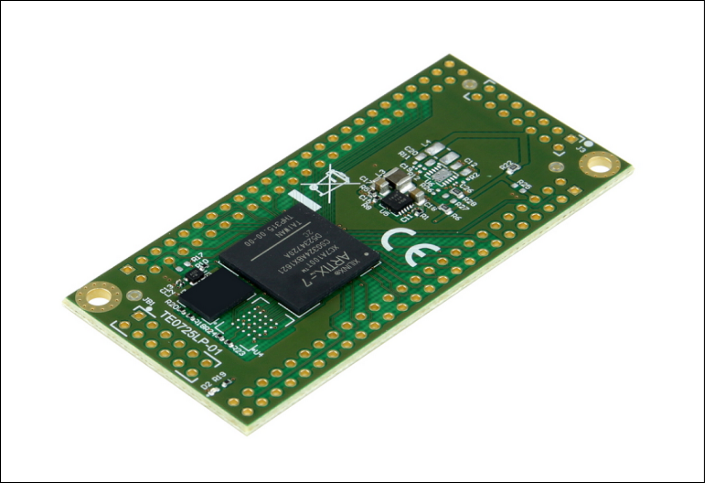
 MicroBlaze Design with Hello TE0725 example in endless loop.

Refer to http://trenz.org/te0725LP-info for the current online version of this manual and other available documentation.

Key Features

Notes :

  • Add basic key futures, which can be tested with the design


  • Vitis/Vivado 2021.2
  • MicroBlaze
  • QSPI
  • I2C
  • UART


Revision History

Notes :

  • add every update file on the download
  • add design changes on description


DateVivadoProject BuiltAuthorsDescription
2022-08-312021.2TE0725LP-test_board_noprebuilt-vivado_2021.2-build_15_20220831152107.zip
TE0725LP-test_board-vivado_2021.2-build_15_20220831152107.zip
Waldemar
Hanemann
  • 2021.2 update
  • Documentation style update
2020-04-202019.2TE0725LP-test_board_noprebuilt-vivado_2019.2-build_10_20200420093012.zip
TE0725LP-test_board-vivado_2019.2-build_10_20200420092959.zip
John Hartfiel
  • 2019.2 update
2019-11-192018.2TE0725LP-test_board_noprebuilt-vivado_2018.2-build_04_20191119080754.zip
TE0725LP-test_board-vivado_2018.2-build_04_20191119080742.zip
John Hartfiel
  • bugfix board part files clk settings
2018-08-162018.2TE0725LP-test_board-vivado_2018.2-build_02_20180816093341.zip
TE0725LP-test_board_noprebuilt-vivado_2018.2-build_02_20180816093354.zip
John Hartfiel
  • 2018.2 update
2018-03-192017.4TE0725LP-test_board-vivado_2017.4-build_07_20180319162005.zip
TE0725LP-test_board_noprebuilt-vivado_2017.4-build_07_20180319162259.zip
John Hartfiel
  • initial release


Release Notes and Know Issues

Notes :
  • add known Design issues and general notes for the current revision
  • do not delete known issue, add fixed version time stamp if  issue fixed


IssuesDescriptionWorkaroundTo be fixed version
No known issues---------


Requirements

Software

Notes :

  • list of software which was used to generate the design


SoftwareVersionNote
Vitis2021.2needed, Vivado is included into Vitis installation


Hardware

Notes :

  • list of software which was used to generate the design

Basic description of TE Board Part Files is available on TE Board Part Files.

Complete List is available on <design name>/board_files/*_board_files.csv

Design supports following modules:

Module ModelBoard Part Short NamePCB Revision SupportDDRQSPI FlashEMMCOthersNotes
TE0725LP-01-100-2C   100REV01    NA       32MB       NA         NA                3.3V Input Voltage     
TE0725LP-01-100-2D   100REV01    NA       32MB       NA         NA                1.8V Input Voltage     
TE0725LP-01-100-2L   100REV01    NA       32MB       NA         NA                1.8V Input Voltage     
TE0725LP-01-100-2I   100_2i        REV01    NA       32MB       NA         NA                1.8V Input Voltage     
TE0725LP-01-72C-1    100REV01    NA       32MB       NA         NA                3.3V Input Voltage     
TE0725LP-01-72C-1T   100REV01    NA       32MB       NA         NA                1.8V Input Voltage     
TE0725LP-01-72I-1T   100_2i        REV01    NA       32MB       NA         NA                1.8V Input Voltage     
TE0725LP-01-72C-1U   100REV01    NA       32MB       NA         NA                1.8V Input Voltage     
TE0725LP-01-72C-1H   100REV01    NA       32MB       NA         with hyperflash 3.3V Input Voltage     


Design supports following carriers:

Carrier ModelNotes
---


Additional HW Requirements:

Additional HardwareNotes
TE0790 JTAG ProgrammerImportant: Depending on assembly version, it's not possible to supply module via TE0790. If it's possible, it's not recommended to use TE0790 for power supply( TE0790 TRM#PowerandPower-OnSequence)
External power supply3.3V or 1.8V depending on assembly variant


Content

Notes :

  • content of the zip file

For general structure and of the reference design, see Project Delivery - AMD devices

Design Sources

TypeLocationNotes
Vivado<design name>/block_design
<design name>/constraints
<design name>/ip_lib
Vivado Project will be generated by TE Scripts
Vitis<design name>/sw_libAdditional Software Template for Vitis and apps_list.csv with settings automatically for Vitis app generation


Additional Sources

TypeLocationNotes
------


Prebuilt

Notes :

  • prebuilt files
  • Template Table:

    • File

      File-Extension

      Description

      BIF-File*.bifFile with description to generate Bin-File
      BIN-File*.binFlash Configuration File with Boot-Image (Zynq-FPGAs)
      BIT-File*.bitFPGA (PL Part) Configuration File
      DebugProbes-File*.ltxDefinition File for Vivado/Vivado Labtools Debugging Interface

      Debian SD-Image

      *.img

      Debian Image for SD-Card

      Diverse Reports---Report files in different formats
      Hardware-Platform-Specification-Files*.xsaExported Vivado Hardware Specification for Vitis and PetaLinux
      LabTools Project-File*.lprVivado Labtools Project File

      MCS-File

      *.mcs

      Flash Configuration File with Boot-Image (MicroBlaze or FPGA part only)

      MMI-File

      *.mmi

      File with BRAM-Location to generate MCS or BIT-File with *.elf content (MicroBlaze only)

      OS-Image*.ubImage with Linux Kernel (On Petalinux optional with Devicetree and RAM-Disk)
      Software-Application-File*.elfSoftware Application for Zynq or MicroBlaze Processor Systems

      SREC-File

      *.srec

      Converted Software Application for MicroBlaze Processor Systems


File

File-Extension

Description

BIT-File*.bitFPGA (PL Part) Configuration File
DebugProbes-File*.ltxDefinition File for Vivado/Vivado Labtools Debugging Interface
Diverse Reports---Report files in different formats
Hardware-Platform-Specification-Files*.xsaExported Vivado Hardware Specification for Vitis and PetaLinux
LabTools Project-File*.lprVivado Labtools Project File

MCS-File

*.mcs

Flash Configuration File with Boot-Image (MicroBlaze or FPGA part only)

MMI-File

*.mmi

File with BRAM-Location to generate MCS or BIT-File with *.elf content (MicroBlaze only)

Software-Application-File*.elfSoftware Application for Zynq or MicroBlaze Processor Systems


Download

Reference Design is only usable with the specified Vivado/Vitis/PetaLinux version. Do never use different Versions of Xilinx Software for the same Project.

Reference Design is available on:

Design Flow


Notes :
  • Basic Design Steps

  • Add/ Remove project specific description


Reference Design is available with and without prebuilt files. It's recommended to use TE prebuilt files for first lunch.

Trenz Electronic provides a tcl based built environment based on Xilinx Design Flow.

See also:

The Trenz Electronic FPGA Reference Designs are TCL-script based project. Command files for execution will be generated with "_create_win_setup.cmd" on Windows OS and "_create_linux_setup.sh" on Linux OS.

TE Scripts are only needed to generate the vivado project, all other additional steps are optional and can also executed by Xilinx Vivado/Vitis GUI. For currently Scripts limitations on Win and Linux OS see: Project Delivery Currently limitations of functionality

Caution! Win OS has a 260 character limit for path lengths which can affect the Vivado tools. To avoid this issue, use Virtual Drive or the shortest possible names and directory locations for the reference design (for example "x:\<project folder>")


  1. Run _create_win_setup.cmd/_create_linux_setup.sh and follow instructions on shell:

    ------------------------Set design paths----------------------------
    -- Run Design with: _create_win_setup
    -- Use Design Path: <absolute project path>
    --------------------------------------------------------------------
    -------------------------TE Reference Design---------------------------
    --------------------------------------------------------------------
    -- (0)  Module selection guide, project creation...prebuilt export...
    -- (1)  Create minimum setup of CMD-Files and exit Batch
    -- (2)  Create maximum setup of CMD-Files and exit Batch
    -- (3)  (internal only) Dev
    -- (4)  (internal only) Prod
    -- (c)  Go to CMD-File Generation (Manual setup)
    -- (d)  Go to Documentation (Web Documentation)
    -- (g)  Install Board Files from Xilinx Board Store (beta)
    -- (a)  Start design with unsupported Vivado Version (beta)
    -- (x)  Exit Batch (nothing is done!)
    ----
    Select (ex.:'0' for module selection guide):


  2. Press 0 and enter to start "Module Selection Guide"
  3. Create project and follow instructions of the product selection guide, settings file will be configured automatically during this process.
    • optional for manual changes: Select correct device and Xilinx install path on "design_basic_settings.cmd" and create Vivado project with "vivado_create_project_guimode.cmd"

      Note: Select correct one, see also Vivado Board Part Flow

      1. Create hardware description file (.xsa file) for PetaLinux project and export to prebuilt folder

        TE::hw_build_design -export_prebuilt


        Using Vivado GUI is the same, except file export to prebuilt folder.


  4. Generate Programming Files with Vitis

    TE::sw_run_vitis -all
    TE::sw_run_vitis (optional; Start Vitis from Vivado GUI or start with TE Scripts on Vivado TCL)


    Note: Scripts generate applications and bootable files, which are defined in "sw_lib\apps_list.csv"

    App from Firmware folder will be add into BlockRAM. If you add other app, you must select *.elf

    manually on Vivado


    TCL scripts generate also platform project, this must be done manually in case GUI is used. See Vitis


  5. (optional) Copy Application (hello_te0725.elf) from prebuilt-folder into \firmware\microblaze_0\ and regenerate design with

    TE::hw_build_design -export_prebuilt


Launch


Note:

  • Programming and Startup procedure

Programming

Check Module and Carrier TRMs for proper HW configuration before you try any design.

Xilinx documentation for programming and debugging: Vivado/SDK/SDSoC-Xilinx Software Programming and Debugging

Get prebuilt boot binaries

  1. Run _create_win_setup.cmd/_create_linux_setup.sh and follow instructions on shell
  2. Press 0 and enter to start "Module Selection Guide"
    1. Select assembly version
    2. Validate selection
    3. Select create and open delivery binary folder

      Note: Folder "<project folder>\_binaries_<Article Name>" with subfolder "boot_<app name>" for different applications will be generated


QSPI

  1. Connect JTAG and power on carrier with module
  2. Open Vivado Project with "vivado_open_existing_project_guimode.cmd" or if not created, create with "vivado_create_project_guimode.cmd"


    TE::pr_program_flash -swapp hello_te0725


  3. Press the reset button to start the application and see the output in the console


SD

Not used on this Example.

JTAG

  1. Connect JTAG and power on PCB
  2. Open Vivado HW Manager
  3. Program FPGA with Bitfile from "prebuilt\hardware\<short dir>\"

Usage

  1. Prepare HW like described on section Programming
  2. Connect UART USB (most cases same as JTAG)

  3. 1. FPGA Loads Bitfile from Flash

    3. Hello Trenz will be run on UART console.

      info: Do not reboot, if Bitfile programming over JTAG is used as programming method.

    1. UART

      Open Serial Console (e.g. putty) Hello TE0725 will run on endless loop.

      1. Speed: 9600
      2. COM Port: Win OS, see device manager, Linux OS see  dmesg |grep tty  (UART is *USB1)

        Power On PCB (Do not restart, if you use Bitfile programming)


System Design - Vivado


Note:

  • Description of Block Design, Constrains... BD Pictures from Export...

Block Design

Constraints

Basic module constraints

set_property BITSTREAM.GENERAL.COMPRESS TRUE [current_design]
set_property BITSTREAM.CONFIG.CONFIGRATE 66 [current_design]
set_property CONFIG_VOLTAGE 1.8 [current_design]
set_property CFGBVS GND [current_design]
set_property BITSTREAM.CONFIG.SPI_32BIT_ADDR YES [current_design]
set_property BITSTREAM.CONFIG.SPI_BUSWIDTH 4 [current_design]
set_property BITSTREAM.CONFIG.M1PIN PULLNONE [current_design]
set_property BITSTREAM.CONFIG.M2PIN PULLNONE [current_design]
set_property BITSTREAM.CONFIG.M0PIN PULLNONE [current_design]

set_property BITSTREAM.CONFIG.USR_ACCESS TIMESTAMP [current_design]

Design specific constraints

---

Software Design - Vitis


Note:
  • optional chapter separate

  • sections for different apps

For SDK project creation, follow instructions from:

Vitis

Application

----------------------------------------------------------

FPGA Example

scu

MCS Firmware to configure SI5338 and Reset System.

srec_spi_bootloader

TE modified 2019.2 SREC

Bootloader to load app or second bootloader from flash into DDR

Descriptions:

  • Modified Files: blconfig.h, bootloader.c
  • Changes:
    • Add some console outputs and changed bootloader read address.
    • Add bugfix for 2018.2 qspi flash

xilisf_v5_11

TE modified 2019.2 xilisf_v5_11

  • Changed default Flash type to 5.

----------------------------------------------------------

Zynq Example:

zynq_fsbl

TE modified 2019.2 FSBL

General:

  • Modified Files:main.c, fsbl_hooks.h/.c (search for 'TE Mod' on source code)
  • Add Files: te_fsbl_hooks.h/.c(for hooks and board)\n\

  • General Changes: 
    • Display FSBL Banner and Device ID

Module Specific:

  • Add Files: all TE Files start with te_*
    • READ MAC from EEPROM and make Address accessible by UBOOT (need copy defines on uboot  platform-top.h)
    • CPLD access
    • Read CPLD Firmware and SoC Type
    • Configure Marvell PHY

zynq_fsbl_flash

TE modified 2019.2 FSBL

General:

  • Modified Files: main.c
  • General Changes:
    •  Display FSBL Banner
    • Set FSBL Boot Mode to JTAG
    • Disable Memory initialisation

ZynqMP Example:

----------------------------------------------------------

zynqmp_fsbl

TE modified 2019.2 FSBL

General:

  • Modified Files: xfsbl_main.c, xfsbl_hooks.h/.c, xfsbl_board.h/.c(search for 'TE Mod' on source code)
  • Add Files:  te_xfsbl_hooks.h/.c (for hooks and board)\n\
  • General Changes: 
    • Display FSBL Banner and Device Name

Module Specific:

  • Add Files: all TE Files start with te_*
    • Si5338 Configuration
    • ETH+OTG Reset over MIO

zynqmp_fsbl_flash

TE modified 2019.2 FSBL

General:

  • Modified Files: xfsbl_initialisation.c, xfsbl_hw.h, xfsbl_handoff.c, xfsbl_main.c
  • General Changes:
    •  Display FSBL Banner
    • Set FSBL Boot Mode to JTAG
    • Disable Memory initialisation


zynqmp_pmufw

Xilinx default PMU firmware.

----------------------------------------------------------

General Example:

hello_te0820

Hello TE0820 is a Xilinx Hello World example as endless loop instead of one console output.

u-boot

U-Boot.elf is generated with PetaLinux. Vitis  is used to generate Boot.bin.

Template location: "<project folder>\sw_lib\sw_apps\"

hello_te0725

Trenz Hello TE0725 example as endless loop. Output on console.

Template location: \sw_lib\sw_apps\hello_te0725

The printed Text can be modified.


Additional Software


Note:
  • Add description for other Software, for example SI CLK Builder ...
  • SI5338 and SI5345 also Link to:

No additional software is needed.

Appx. A: Change History and Legal Notices

Document Change History

To get content of older revision  got to "Change History"  of this page and select older document revision number.

  • Note this list must be only updated, if the document is online on public doc!
  • It's semi automatically, so do following
    • Add new row below first

    • Copy "Page Information Macro(date)" Macro-Preview, Metadata Version number, Author Name and description to the empty row. Important Revision number must be the same as the Wiki document revision number Update Metadata = "Page Information Macro (current-version)" Preview+1 and add Author and change description. --> this point is will be deleted on newer pdf export template

    • Metadata is only used of compatibility of older exports


DateDocument Revision

Authors

Description

  • 2021.2 update
  • Documentation style update
2020-04-20


v.9


John Hartfiel

  • 2019.2 release
  • docu update
2019-11-19v.8John Hartfiel
  • bugfix board part files
2018-08-16v.6John Hartfiel
  • 2018.2 release

2018-06-05

v.5John Hartfiel
  • Typo correction UART Speed

2018-03-19

v.3John Hartfiel
  • 2017.4 release

All


Legal Notices


<style>
.wiki-content .columnLayout .cell.aside {
width: 0%;
}</style>


Table of contents