Design Name is always "TE Series Name" + Design name, for example "TE0720 Test Board"
|
Important General Note:
|
Overview
Notes :
|
Refer to http://trenz.org/te0741-info for the current online version of this manual and other available documentation.
This example shows how to reconfigure SI5338 with the MicroBlaze_MCS and monitor the CLKs. An additional MicroBlaze is added for running the Hello_TE0741 standalone application.
Key Features
Notes :
|
|
Revision History
Notes :
|
|
Release Notes and Know Issues
Notes :
|
|
Requirements
Software
Notes :
|
|
Hardware
Notes :
|
Basic description of TE Board Part Files is available on TE Board Part Files.
Complete List is available on "<project folder>\board_files\*_board_files.csv"
Design supports following modules:
|
Design supports following carriers:
*used as reference |
Additional HW Requirements:
*used as reference |
Content
Notes :
|
For general structure and usage of the reference design, see Project Delivery - AMD devices
Design Sources
|
Additional Sources
|
Prebuilt
Notes :
|
|
Download
Reference Design is only usable with the specified Vivado/Vitis/PetaLinux version. Do never use different Versions of AMD Software for the same Project.
|
Reference Design is available on:
Design Flow
Notes :
|
Reference Design is available with and without prebuilt files. It's recommended to use TE prebuilt files for first launch. |
Trenz Electronic provides a tcl based built environment based on AMD Design Flow.
See also:
The Trenz Electronic FPGA Reference Designs are TCL-script based project. Command files for execution will be generated with "_create_win_setup.cmd" on Windows OS and "_create_linux_setup.sh" on Linux OS.
TE Scripts are only needed to generate the vivado project, all other additional steps are optional and can also executed by AMD Vivado/Vitis GUI. For currently Scripts limitations on Win and Linux OS see: Project Delivery Currently limitations of functionality
Caution! Win OS has a 260 character limit for path lengths which can affect the Vivado tools. To avoid this issue, use Virtual Drive or the shortest possible names and directory locations for the reference design (for example "x:\<project folder>") |
Run _create_win_setup.cmd/_create_linux_setup.sh and follow instructions on shell:
------------------------Set design paths----------------------------
-- Run Design with: _create_win_setup
-- Use Design Path: <absolute project path>
--------------------------------------------------------------------
-------------------------TE Reference Design---------------------------
--------------------------------------------------------------------
-- (0)  Module selection guide, project creation...prebuilt export...
-- (1)  Create minimum setup of CMD-Files and exit Batch
-- (2)  Create maximum setup of CMD-Files and exit Batch
-- (3)  (internal only) Dev
-- (4)  (internal only) Prod
-- (c)  Go to CMD-File Generation (Manual setup)
-- (d)  Go to Documentation (Web Documentation)
-- (g)  Install Board Files from Xilinx Board Store (beta)
-- (a)  Start design with unsupported Vivado Version (beta)
-- (x)  Exit Batch (nothing is done!)
----
Select (ex.:'0' for module selection guide):
- Press 0 and enter to start "Module Selection Guide"
- Create project and follow instructions of the product selection guide, settings file will be configured automatically during this process.
optional for manual changes: Select correct device and Xilinx install path on "design_basic_settings.cmd" and create Vivado project with "vivado_create_project_guimode.cmd"
Note: Select correct one, see also Vivado Board Part Flow
Create hardware description file (.xsa file) and export to prebuilt folder
TE::hw_build_design -export_prebuilt
Using Vivado GUI is the same, except file export to prebuilt folder.
- Generate Programming Files with Vitis
Run on Vivado TCL:
TE::sw_run_vitis -all
- Copy "\prebuilt\software\<short name>\hello_te0741.elf" into "\firmware\microblaze_0\"
- (optional) Copy "\prebuilt\software\<short name>\scu.elf" into "\firmware\microblaze_mcs_0\"
Regenerate Vivado Project or Update Bitfile only, with new "hello_te0741.elf" and "scu.elf"
This step depends on AMD Device/Hardware
for Zynq-7000 series
- copy u-boot.elf, u-boot.dtb, system.dtb, image.ub and boot.scr from "<plnx-proj-root>/images/linux" to prebuilt folder
for ZynqMP
- copy u-boot.elf, u-boot.dtb, system.dtb, bl31.elf, image.ub and boot.scr from "<plnx-proj-root>/images/linux" to prebuilt folder
for Microblaze
- ...Regenerate Vivado Project or Update Bitfile only with "hello_te0741.elf" and "scu.elf"
TCL scripts generate also platform project, this must be done manually in case GUI is used. See Vitis
Launch
Note:
|
Programming
Check Module and Carrier TRMs for proper HW configuration before you try any design. Reference Design is also available with prebuilt files. It's recommended to use TE prebuilt files for first launch. |
AMD documentation for programming and debugging: Vivado/Vitis/SDSoC-Xilinx Software Programming and Debugging
Get prebuilt boot binaries
- Run _create_win_setup.cmd/_create_linux_setup.sh and follow instructions on shell
- Press 0 and enter to start "Module Selection Guide"
- Select assembly version
- Validate selection
Select create and open delivery binary folder
Note: Folder "<project folder>\_binaries_<Article Name>" with subfolder "boot_<app name>" for different applications will be generated
QSPI
- Connect JTAG and power on carrier with module
Open Vivado Project with "vivado_open_existing_project_guimode.cmd" or if not created, create with "vivado_create_project_guimode.cmd"
TE::pr_program_flash -swapp hello_te0741
To program with Vitis/Vivado GUI, use special FSBL (fsbl_flash) on setup
SD-Boot mode
Not used on this Example.
JTAG
- Connect JTAG and power on PCB
- Open Vivado HW Manager
- Program FPGA with Bitfile from "prebuilt\hardware\<short dir>\"
Usage
- Prepare HW like described on section Programming
- Connect UART USB (most cases same as JTAG)
Select QSPI as Boot Mode
Note: See TRM of the Carrier, which is used.
Power On PCB
1. FPGA Loads Bitfile from Flash
2. MCS Firmware configure SI5338 and starts Microblaze
3. Hello TE0741 from Bitfile Example will be run on UART console.
info: Do not reboot, if Bitfile programming over JTAG is used as programming method.
UART
Open Serial Console (e.g. putty)
- Speed: 9600
- COM Port: Win OS, see device manager, Linux OS see dmesg |grep tty (UART is *USB1)

This step depends on Xilinx Device/Hardware
for Zynq-7000 series
1. Zynq Boot ROM loads FSBL from SD/QSPI into OCM,
2. FSBL init the PS, programs the PL using the bitstream and loads U-boot from SD/QSPI into DDR,
3. U-boot loads Linux (image.ub) from SD/QSPI/... into DDR
for ZynqMP???
1. ZynqMP Boot ROM loads FSBL from SD/QSPI into OCM,
2. FSBL init the PS, programs the PL using the bitstream and loads PMU, ATF and U-boot from SD/QSPI into DDR,
3. U-boot loads Linux (image.ub) from SD/QSPI/... into DDR
for Microblaze with Linux
1. FPGA Loads Bitfile from Flash,
2. MCS Firmware configure SI5338 and starts Microblaze, (only if mcs is available)
3. SREC Bootloader from Bitfile Firmware loads U-Boot into DDR (This takes a while),
4. U-boot loads Linux from QSPI Flash into DDR
for native FPGA
...
Vivado HW Manager
Note:
|
Open Vivado HW-Manager and add VIO signal to dashboard (*.ltx located on prebuilt folder)
- Control:
- LED_D1/D2 control. Control LED D4 with XIO.
- SI5338 25MHz REF CLK Enable
- MGT Enable
- LED_D1/D2 control. Control LED D4 with XIO.
- Monitoring:
- Set radix from VIO signals (MGT...) to unsigned integer.
- Note: Frequency Counter is inaccurate and displayed unit is Hz
- MGT REFCLK1~125MHz, GT_REFCLK3~156,25MHz (default off, configured with MCS Firmware)
- MGT Power Monitoring
 |
System Design - Vivado
Note:
|
Block Design
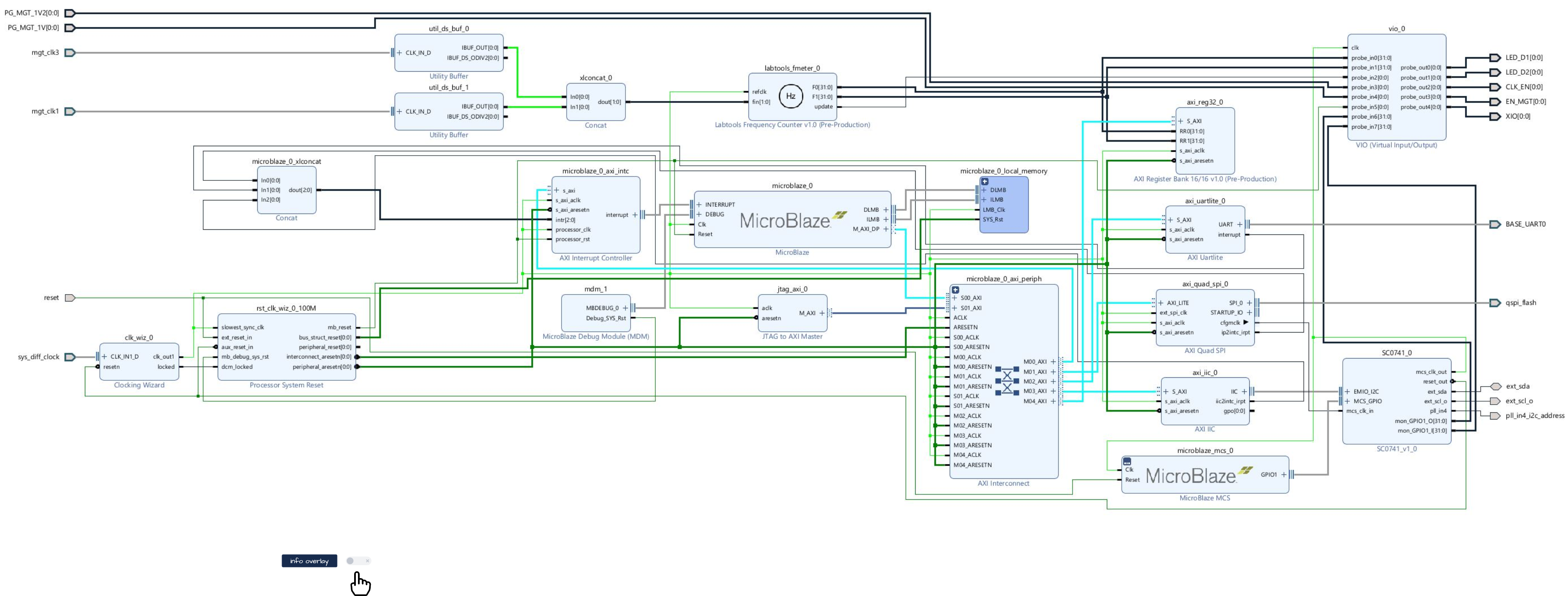 |
Note:
|
Constraints
Basic module constraints
set_property BITSTREAM.GENERAL.COMPRESS TRUE [current_design] set_property BITSTREAM.CONFIG.CONFIGRATE 66 [current_design] set_property CONFIG_VOLTAGE 3.3 [current_design] set_property CFGBVS VCCO [current_design] set_property CONFIG_MODE SPIx4 [current_design] set_property BITSTREAM.CONFIG.SPI_32BIT_ADDR YES [current_design] set_property BITSTREAM.CONFIG.SPI_BUSWIDTH 4 [current_design] set_property BITSTREAM.CONFIG.M1PIN PULLNONE [current_design] set_property BITSTREAM.CONFIG.M2PIN PULLNONE [current_design] set_property BITSTREAM.CONFIG.M0PIN PULLNONE [current_design] set_property BITSTREAM.CONFIG.USR_ACCESS TIMESTAMP [current_design |
Design specific constraints
#LED
set_property PACKAGE_PIN D26 [get_ports {LED_D1[0]}]
set_property IOSTANDARD LVCMOS33 [get_ports {LED_D1[0]}]
set_property PACKAGE_PIN E26 [get_ports {LED_D2[0]}]
set_property IOSTANDARD LVCMOS33 [get_ports {LED_D2[0]}]
#MGT Power
set_property PACKAGE_PIN G25 [get_ports {PG_MGT_1V2[0]}]
set_property IOSTANDARD LVCMOS33 [get_ports {PG_MGT_1V2[0]}]
set_property PACKAGE_PIN K23 [get_ports {PG_MGT_1V[0]}]
set_property IOSTANDARD LVCMOS33 [get_ports {PG_MGT_1V[0]}]
set_property PACKAGE_PIN H22 [get_ports {EN_MGT[0]}]
set_property IOSTANDARD LVCMOS33 [get_ports {EN_MGT[0]}]
#SI5338 CLK
set_property PACKAGE_PIN C26 [get_ports {CLK_EN[0]}]
set_property IOSTANDARD LVCMOS33 [get_ports {CLK_EN[0]}]
#I2C PLL SI5338
set_property PACKAGE_PIN A20 [get_ports ext_scl_o]
set_property IOSTANDARD LVCMOS33 [get_ports ext_scl_o]
set_property PACKAGE_PIN B21 [get_ports ext_sda]
set_property IOSTANDARD LVCMOS33 [get_ports ext_sda]
set_property PACKAGE_PIN B20 [get_ports pll_in4_i2c_address]
set_property IOSTANDARD LVCMOS33 [get_ports pll_in4_i2c_address]

#OneWire
set_property IOSTANDARD LVCMOS33 [get_ports XIO]
set_property PACKAGE_PIN H26 [get_ports XIO]


set_property IOSTANDARD LVCMOS33 [get_ports reset]
set_property PACKAGE_PIN L23 [get_ports reset]
set_property PACKAGE_PIN C23 [get_ports qspi_flash_ss_io]
set_property IOSTANDARD LVCMOS33 [get_ports qspi_flash_ss_io]
set_property PACKAGE_PIN B24 [get_ports qspi_flash_io0_io]
set_property IOSTANDARD LVCMOS33 [get_ports qspi_flash_io0_io]
set_property PACKAGE_PIN A25 [get_ports qspi_flash_io1_io]
set_property IOSTANDARD LVCMOS33 [get_ports qspi_flash_io1_io]
set_property PACKAGE_PIN B22 [get_ports qspi_flash_io2_io]
set_property PACKAGE_PIN A22 [get_ports qspi_flash_io3_io]
set_property IOSTANDARD LVCMOS33 [get_ports qspi_flash_io2_io]
set_property IOSTANDARD LVCMOS33 [get_ports qspi_flash_io3_io]
#set_property C_CLK_INPUT_FREQ_HZ 300000000 [get_debug_cores dbg_hub]
#set_property C_ENABLE_CLK_DIVIDER false [get_debug_cores dbg_hub]
#set_property C_USER_SCAN_CHAIN 1 [get_debug_cores dbg_hub]
#connect_debug_port dbg_hub/clk [get_nets clk] |
#Fmeter can be ignored, it's only simple measurement

set_false_path -from [get_pins {msys_i/labtools_fmeter_0/U0/FMETER_gen[*].COUNTER_F_inst/bl.DSP48E_2/CLK}] -to [get_pins {msys_i/labtools_fmeter_0/U0/F_reg[*]/D}]

set_false_path -from [get_pins msys_i/labtools_fmeter_0/U0/toggle_reg/C] -to [get_pins {msys_i/labtools_fmeter_0/U0/FMETER_gen[*].COUNTER_F_inst/bl.DSP48E_2/RSTC}]
set_false_path -from [get_pins msys_i/labtools_fmeter_0/U0/toggle_reg/C] -to [get_pins {msys_i/labtools_fmeter_0/U0/FMETER_gen[*].COUNTER_F_inst/bl.DSP48E_2/RSTA}]
set_false_path -from [get_pins msys_i/labtools_fmeter_0/U0/toggle_reg/C] -to [get_pins {msys_i/labtools_fmeter_0/U0/FMETER_gen[*].COUNTER_F_inst/bl.DSP48E_2/RSTB}]
set_false_path -from [get_pins msys_i/labtools_fmeter_0/U0/toggle_reg/C] -to [get_pins {msys_i/labtools_fmeter_0/U0/FMETER_gen[*].COUNTER_F_inst/bl.DSP48E_2/CEALUMODE}]
set_false_path -from [get_pins msys_i/labtools_fmeter_0/U0/toggle_reg/C] -to [get_pins {msys_i/labtools_fmeter_0/U0/FMETER_gen[*].COUNTER_F_inst/bl.DSP48E_2/RSTCTRL}]


#set_false_path -from [get_clocks -of_objects [get_pins msys_i/clk_wiz_0/inst/mmcm_adv_inst/clk_out1]] -to [get_clocks {msys_i/util_ds_buf_0/U0/IBUF_OUT[0]}]
#set_false_path -from [get_clocks -of_objects [get_pins msys_i/clk_wiz_0/inst/mmcm_adv_inst/clk_out1]] -to [get_clocks {msys_i/util_ds_buf_1/U0/IBUF_OUT[0]}]

set_false_path -from [get_clocks -of_objects [get_pins msys_i/clk_wiz_0/inst/mmcm_adv_inst/CLKOUT0]] -to [get_clocks mgt_clk1_clk_p]
set_false_path -from [get_clocks -of_objects [get_pins msys_i/clk_wiz_0/inst/mmcm_adv_inst/CLKOUT0]] -to [get_clocks mgt_clk3_clk_p |
Software Design - Vitis
Note:
|
For Vitis project creation, follow instructions from:
Application
---------------------------------------------------------- FPGA Example scuMCS Firmware to configure SI5338 and Reset System. srec_spi_bootloaderTE modified 2021.2 SREC Bootloader to load app or second bootloader from flash into DDR Descriptions:
xilisf_v5_11TE modified 2021.2 xilisf_v5_11
---------------------------------------------------------- Zynq Example: fsblTE modified 2021.2 FSBL General:
Module Specific:
fsbl_flashTE modified 2021.2 FSBL General:
ZynqMP Example: ---------------------------------------------------------- zynqmp_fsblTE modified 2021.2 FSBL General:
Module Specific:
zynqmp_fsbl_flashTE modified 2021.2 FSBL General:
zynqmp_pmufwXilinx default PMU firmware. ---------------------------------------------------------- General Example: hello_te0820Hello TE0820 is a Xilinx Hello World example as endless loop instead of one console output. u-bootU-Boot.elf is generated with PetaLinux. Vitis is used to generate Boot.bin. |
Template location: "<project folder>\sw_lib\sw_apps\"
SCU
MCS Firmware to configure SI5338 and Reset System.
Template location: \sw_lib\sw_apps\scu
Hello TE0741
Xilinx Hello World example as endless loop with reading Clock registers from fmeter IP
Template location: \sw_lib\sw_apps\hello_te0741
Additional Software
SI5338
File location "<project folder>\misc\Si5338\Si5338-*.slabtimeproj"
General documentation how you work with this project will be available on Si5338
| Note: |
App. A: Change History and Legal Notices
Document Change History
To get content of older revision go to "Change History" of this page and select older document revision number.
|
|
Legal Notices
|
|