In this section you must explain how to power on the board and run the Reference Design (test board) on the particular module. The main points must be mentioned are: |
Table of Contents 
|
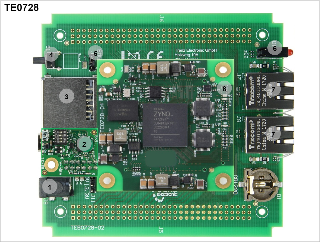
TEB0728 with TE0728
Overview
- Barrel Jack Power Supply
- XMOD JTAG Adapter
- SD card holder
- Reset
- Boot mode Jumper
- Carrier LEDs (Red,Yellow,Green) D1
- Ethernet Socket
- Module LEDs (Green D4, Red D8)
Power supply
The input power supply must be mentioned. |
Single 5V power supply with minimum current capability of 2.5A is recommended to power on the board.
DIP-Switches and Push Buttons
Explain all DIP switches functionality. |
There is a switch (S1) which is connected to RESET signal, it resets the system entirely.

Overview 4 | Connected to | B2B | Active Level |
|---|
S1 | RESET | J2-7 | Active High |
|
There is no DIPs on TE0728. In case of TE0790 (XMOD) usage, see DIPs mode.
Jumpers
Explain all Jumpers functionality and connection. |
| Overview 5 | Connected to | B2B | Note |
|---|
| J4 | Boot_R | J2-11 | Open: QSPI | | Short: SD Card |
|
LEDs
Explain all user LEDs functionality and connections. |
There are three user LEDs on the carrier TEB0728 which can be used for variant purposes.
| Overview 6 | Color | Connected to | B2B | Active Level | Note |
|---|
| D1-A | Red | MIO48 | J2-30 | Active high | User LED | | D1-B | Yellow | MIO49 | J2-38 | Active high | User LED | | D1-C | Green | MIO50 | J2-36 | Active high | User LED |
|
Furthermore, there are two user LEDs on module TE0728.
| Overview 8 | Color | Connected to | B2B | Active Level | Note |
|---|
| D4 | Green | Bank33 pin V18 | - | Active high | User LED | | D9 | Green | DONE_0 |
|
| DONE pin | | D8 | Red | MIO7 | - | Active high | User LED |
|
JTAG/UART
Explain JTAG or UART connection breifly. |
JTAG and UART connections are available through XMOD JTAG adapter. For more information refer to TE0790.
DIP Switch on the XMOD JTAG adapter must be set like the following table.
Reference Designs
In this Section you must refer to the Reference Design (Test board) for the particular module. For Example: TE0728 Reference Designs |
Notes
In this Section you must refer to the Resources Page for the particular module. For Example: TE0728 Resources |