Important General Note:
- If some section is configurable and depends on Firmware, please refer to the addition page (for example CPLD). If not available, add note, that this part is configurable
Designate all graphics and pictures with a number and a description, Use "Scroll Title" macro
- Use "Scroll Title" macro for pictures and table labels. Figure number must be set manually at the moment (automatically enumeration is planned by scrollPDF)
Figure template:
Create DrawIO object here: Attention if you copy from other page, objects are only linked.
image link to the generate DrawIO PNG file of this page. This is a workaround until scroll pdf export bug is fixed
Table template:
- Layout macro can be use for landscape of large tables
Example Comment 1 2
The anchors of the Scroll Title should be named consistant across TRMs. A incomplete list of examples is given below
<type>_<main section>_<name>
- type: Figure, Table
- main section:
- "OV" for Overview
- "SIP" for Signal Interfaces and Pins,
- "OBP" for On board Peripherals,
- "PWR" for Power and Power-On Sequence,
- "B2B" for Board to Board Connector,
- "TS" for Technical Specification
- "VCP" for Variants Currently in Production
- "RH" for Revision History
- name: custom, some fix names, see below
- Fix names:
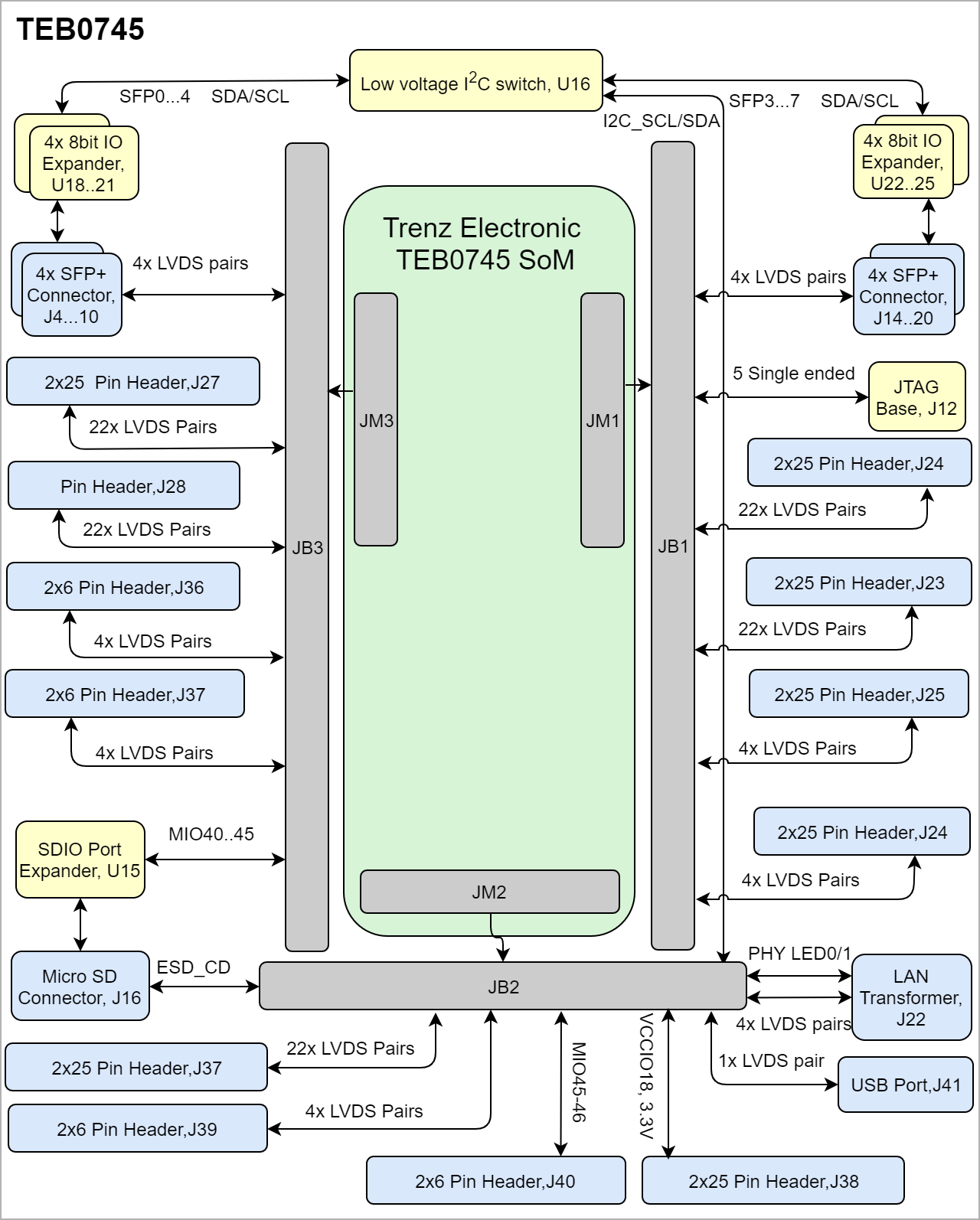
"Figure_OV_BD" for Block Diagram
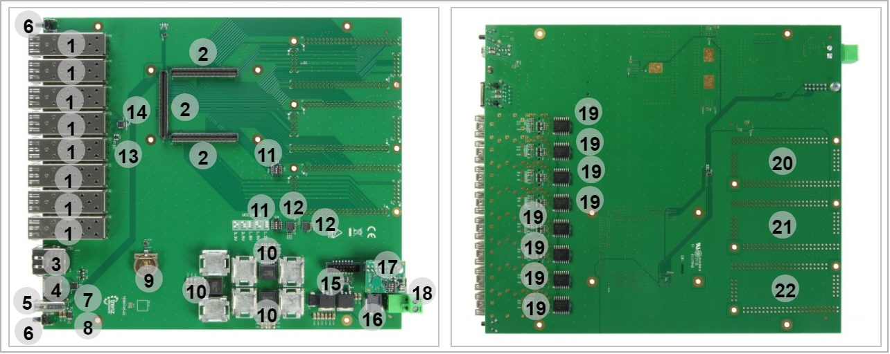
"Figure_OV_MC" for Main Components
"Table_OV_IDS" for Initial Delivery State
"Table_PWR_PC" for Power Consumption
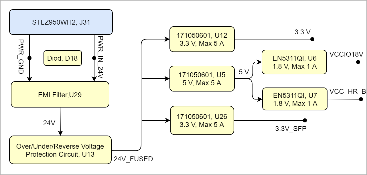
- "Figure_PWR_PD" for Power Distribution
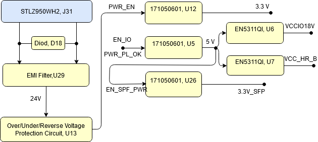
- "Figure_PWR_PS" for Power Sequence
- "Figure_PWR_PM" for Power Monitoring
- "Table_PWR_PR" for Power Rails
- "Table_PWR_BV" for Bank Voltages
"Table_TS_AMR" for Absolute_Maximum_Ratings
"Table_TS_ROC" for Recommended_Operating_Conditions
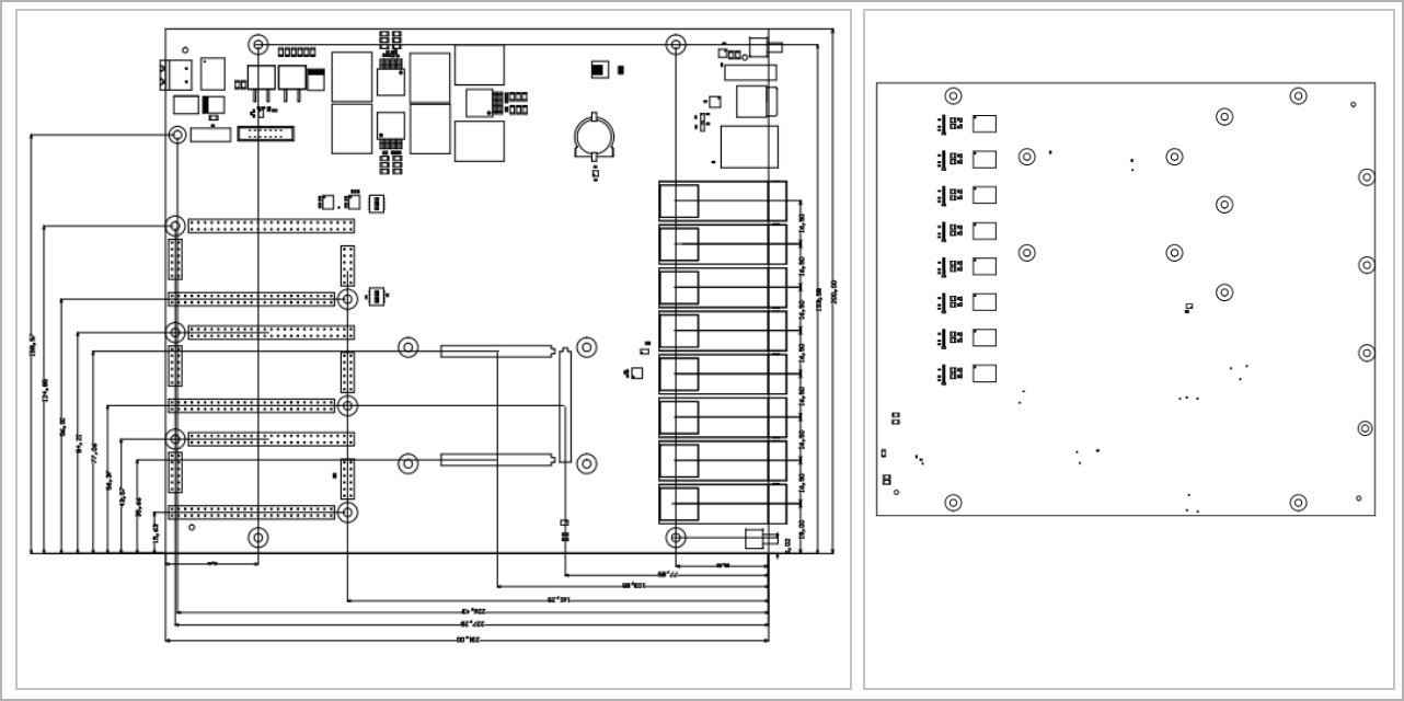
- "Figure_TS_PD" for Physical_Dimensions
- "Table_VCP_SO" for TE_Shop_Overview
"Table_RH_HRH" for Hardware_Revision_History
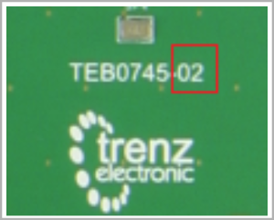
- "Figure_RH_HRN" for Hardware_Revision_Number
- "Table_RH_DCH" for Document_Change_History
- Use Anchor in the document: add link macro and add "#<anchorname>
- Refer to Anchror from external : <page url>#<pagename without space characters>-<anchorname>
- Use "Scroll Title" macro for pictures and table labels. Figure number must be set manually at the moment (automatically enumeration is planned by scrollPDF)

