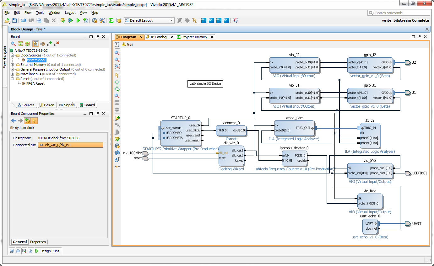
LabX Demo
This design converts TE0725 into mini lab instrument:
- I/O Monitor and excerciser (all 84 I/O in B2B connectors)
- 84 Channel Logic Analyzer, 4K deep (on A15T, an be larger with larger FPGA)
- UART Echo with 1 Channel Logic Analyzer, 128K deep
- 2 Channel Frequency Counter (each channel can use any pin from one connector)
- 2 Channel Duty Cycle Instrument (each channel can use any pin from one connector)
- POF Cable testing, Frequency, Duty and Logic Analyzer
| ILA Core Name | Sample Rate | Depth | Connection |
|---|---|---|---|
| xmod_uart | 10 MS/s | 128K | UART RXD in XMOD connector |
| POF | 1 GS/s | 4K | LVDS input from POF fibre receiver |
| J1_J2 | 100 MS/s | 4K | J1: 42 pins, J2: 42 pins |
Sample depths can be increased for all modules with FPGA's larger than A15T.
| Channel Name | Measurement Type | Connection |
|---|---|---|
| CFCLK | Frequency | Free running configuration clock, nominal 66MHz |
| J1_FREQ | Frequency | input multiplexer, from any pin in J1 |
| J1_DUTY | Duty Cycle | input multiplexer, from any pin in J1 |
| J2_FREQ | Frequency | input multiplexer, from any pin in J2 |
| J2_DUTY | Duty Cycle | input multiplexer, from any pin in J2 |
| POF_FREQ | Frequency | LVDS input from POF receiver |
| POF_DUTY | Duty Cycle | LVDS input from POF receiver |
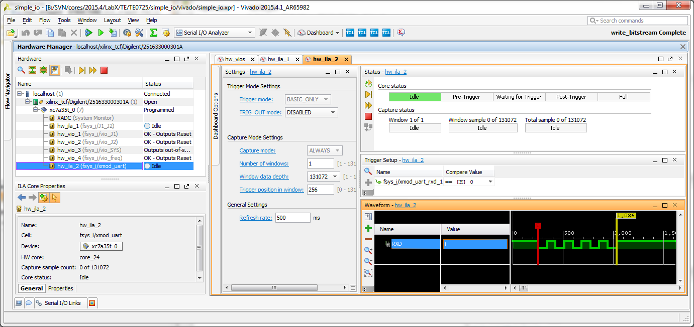
Example screenshot, Uppercase "U" (HEX 0x55, binary 01010101) was sent from UART at 115200 baud, trigger on RXD logic level 0.
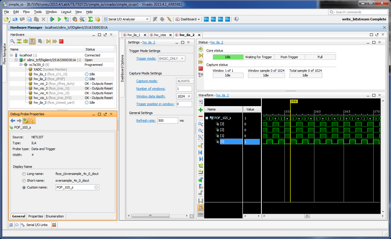
125MHz signal sent to POF cable and received from the LVDS input, captured with 250MHz I/O sample clock, 4 samples per clock at data rate of 1GS/s.
Overview
Content Tools