This is simple demo for DC (Direction Conversion) SDR function use in FPGA, for analog input XADC is used (Zynqberry mic input).
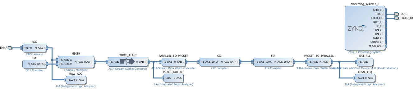
IPI BD for the SDR demo.
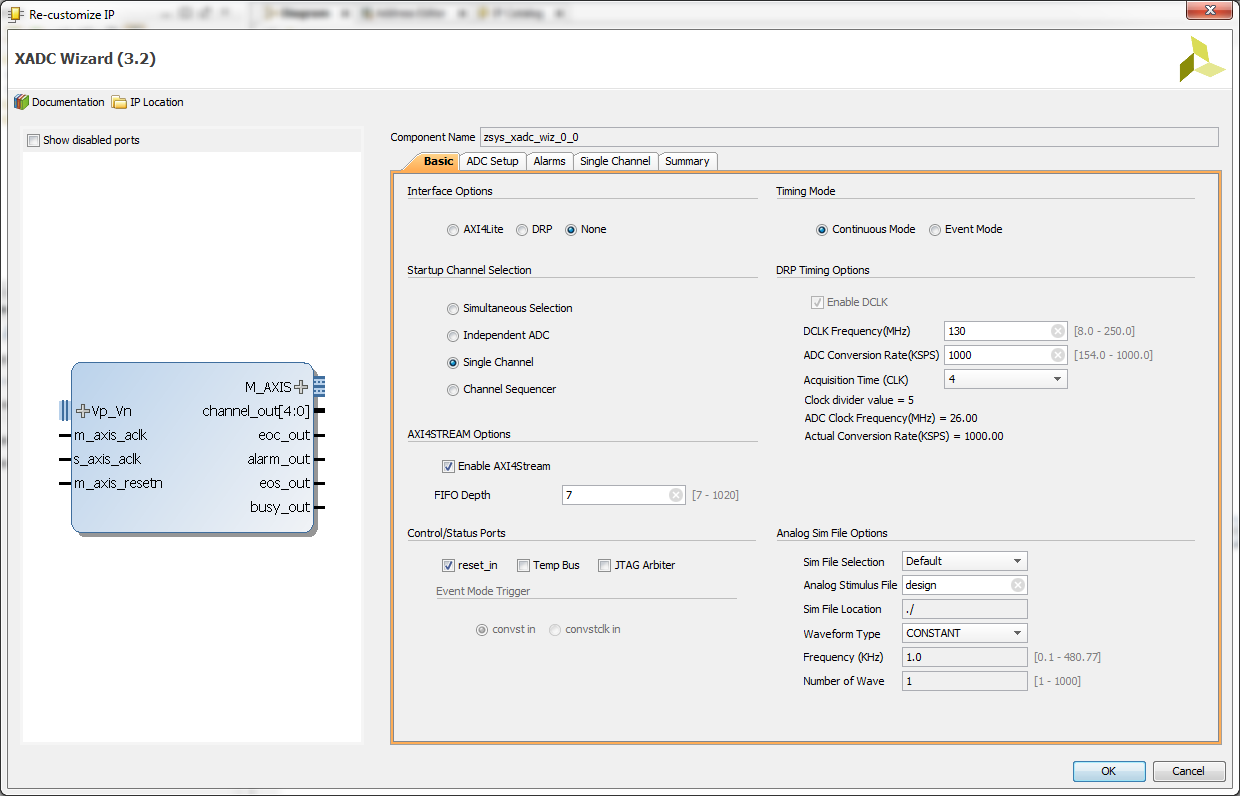
XADC is configured with streaming interface. Clock is set to 130MHz (generated with Clock Wizard) XADC sample rate exactly 1MSPS.
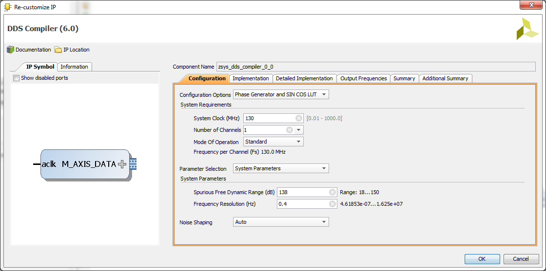
DDS Compiler Wizard is used to generate LO (local oscillator) Sinus and Cosinus outputs. LO output is multiplied with the input from XADC. All AXI4-Streaming components run from single system clock (130MHz). XADC asserts TVALID with the rate of ADC sampling, that is 1 MHz. To make DDS to work at 130MHz TREADY input of the DDS Output stream must be tied to 1.
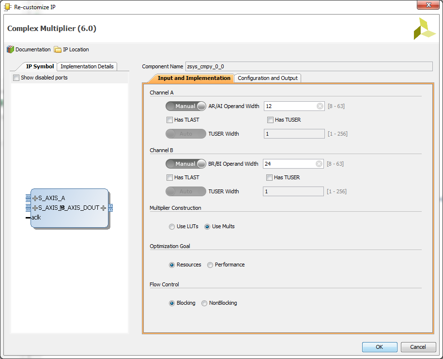
After complex multiplier AXI stream subset converter is used to force TLAST to 1, then AXI stream datawidth converter is used to convert single samples with I and Q values into stream of interleaved I and Q values. This stream is going into CIC block that converts the sampling frequency down.
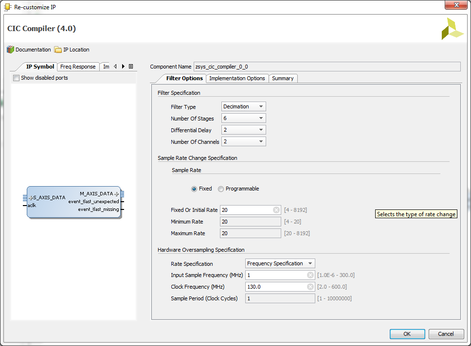
Configuration of the CIC
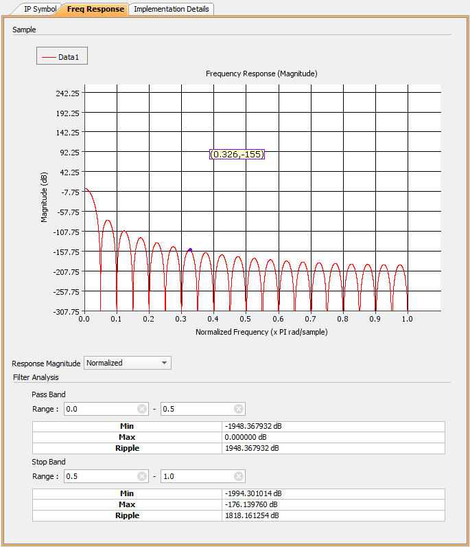
CIC Frequency response.
Downconverted I and Q stream enters a FIR block that also reduces sample rate by 2.
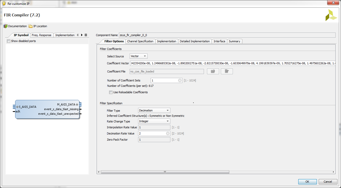
Configuration of the FIR.
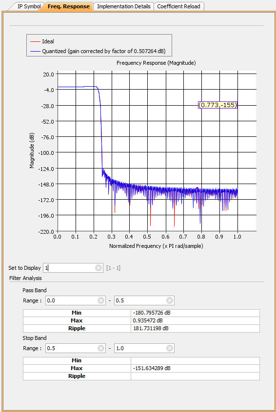
Frequency response of the FIR Filter.
After FIR filter AXI stream datawidht converter is used again to get convert the interleaved samples of I and Q as single AXIS stream TDATA word. The processing is terminated by AXI stream DEVNULL that eats all. For visualization and data capture ILA Logic Analyzer IP cores are inserted. For test purposes the LO frequency was set to 134KHz (this is close to WSPR band where beacons are expected to be present in frequency band).
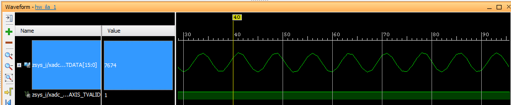
XADC Raw data, capturing 135KHz signal from Zynqberry mic input.

I and Q immediatly after the complex multiplier
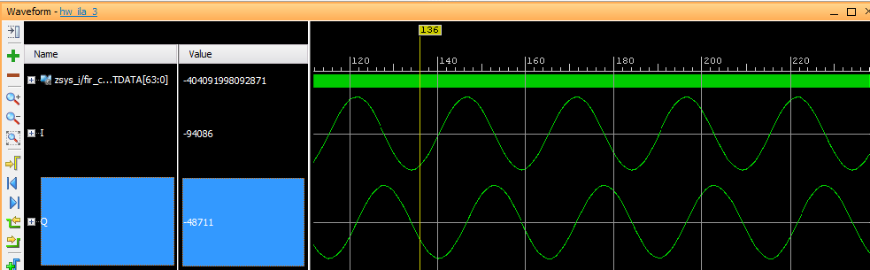
I and Q data after DDC and FIR with input signal at 135KHz, 1 KHz signal is seen 135KHz - 134MHz = 1KHz.
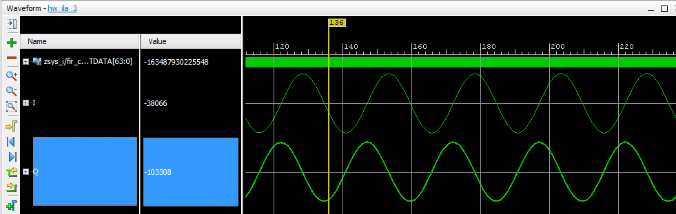
Output with 133KHz input signal, 1KHz signal is seen 133KHz - 134KHz = -1KHz, the phase of I and Q is now different.
Overview
Content Tools