USB device and host
Unlike RS-232 and similar serial interfaces where the format of data being sent is not defined, USB is made up of several layers of protocols. These protocols are automatically managed by USB FX2 microcontroller and OS device driver.
USB is a host centric polled bus, meaning the host controller (the computer in this case) must initiate all transaction. Do not mistake this to mean that the system software must poll the USB. The host controller takes care of polling the bus and can be programmed to issue interrupts to the OS whenever the bus needs attention. The timeslot between SOF and EOF can be used for USB transactions (13 to 133 in a microframe). However the timing for SOF and EOF is very strict and the host initiates only transactions that can be fully completed within the free timeslot.
There is no way for a USB device (TE USB FX2 FPGA module) to "interrupt" its host controller (the host computer) in the same manner as other hardware interrupts. USB does support an Interrupt transfer method, but this is in fact implemented by polling and the latency one can achieve is about 1 ms, but ultimately limited by the host's performance (bInterval: Interval for polling a device during a data transfer, expressed in units of microframes for high-speed devices).
The host initiates all transactions using Token Packets.
There are three types of token packets (and only the USB host can send them):
- In - Informs the USB device that the host wishes to read information.
- Out - Informs the USB device that the host wishes to send information.
- Setup - Used to begin control transfers.
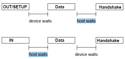
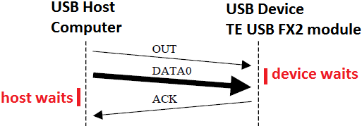
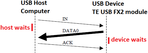
Single USB transaction: OUT/SETUP and IN case.
USB host
TE USB FX2 module is not a a USB host but only an USB device.
The host computer's running the software application is the USB host. => Only the host computer's software could start communication (read/write data, send command and retrieve reply) with TE USB FX2 module.
The USB device (TE USB FX2 FPGA module) is using Hi-Speed USB => Hi-Speed USB device endpoints may only select a maximum data payload size of 512 bytes => bulk endpoint's wMaxPacketSize is 512.
Compliant USB 2.0/1.1 drivers must transmit packets of maximum size (wMaxPacketSize) and then either end the transmission by means of a packet of less than maximum size, or delimit the end of the transmission by means of a zero-length packet. The transmission is not complete until the driver sends a packet smaller than wMaxPacketSize. If the transfer size is an exact multiple of the maximum, the driver must send a zero-length delimiting packet to explicitly terminate the transfer. Delimiting the data transmission with zero-length packets, as required by the USB specification, is the responsibility of the device driver. The system USB stack will not generate these packets automatically. For reference see here.
If a user wants to force a bulk packet with a size of less than wMaxPacketSize, the user should use PKTEND. But it is normally better to pad the data to transmit to 512 bytes (or multiple of this value).
Distribution of Bus Access Time: Frames and Microframes
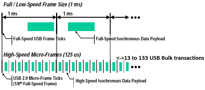
To ensure synchronization between the host and the functions, the USB divides bus time into fixed-length segments. For low- or full-speed buses, the USB divides the bus time into 1 millisecond units, called frames. For a high-speed bus, the USB divides the bus time into 125 microsecond (us) units, called microframes.
USB high speed communication is synchronized in a fixed frame structure. Each frame is 125 us long and begins with an Start-Of-Frame packet (SOF) and is limited by and End-Of-Frame sequence (EOF). Each packet starts with SYNC and ends with and End-Of-Packet (EOP). EOP is variable in size and packet data dependent, for SOF it is always 5 bytes.
Frames and microframes do not correspond to any packet or transaction; in fact, several transactions usually take place during one (micro)frame. The host controller issues a start-of-frame (SOF) packet at the beginning of every (micro)frame. The remainder of the (micro)frame is available for the host controller to carry out transactions (a maximum of 13-133 bulk packet can be used in every microframe aka 125 us, Universal Serial Bus Specification Revision 2.0, Table 5-10. High-speed Bulk Transaction Limits). A transaction may not take place if it cannot be completed in the same (micro)frame (because otherwise the next SOF packet would interrupt the transaction).
It is important to realize that the host controller may rearrange transactions to make better use of the available bandwidth. Of course, two transactions through the same pipe must occur in the correct order, but the transactions of two separate transfers may be reordered at the host controller's discretion.
USB is a packetized protocol where longer blocks of data are normally subdivided into 512-byte packets (in particular for bulk transfer). Each packet contains a header identifying the packet contents, and a CRC at the end of the packet for data integrity. Each packet also requires an ACK from the other side of the link. Start of Frame (SOF) packets are sent every 125 uSec (microframe) to maintain timing on the bus.
Frame and microframe
The subdivision in bulk packets is decided by the Operating System USB section and device driver, not by the SW API (Trenz Electronic, Cypress or libusb(x)). To force the use of a bulk packet by the USB system the user should use PKTEND.
USB device's endpoints: EP1, EP 6 and EP8 are the endpoints mainly used by reference firmware
Endpoints can be described as sources or sinks of data. As the bus is host centric, endpoints occur at the end of the communications channel at the USB function.
Endpoints can also be seen as the interface between the hardware of the function device and the firmware running on the function device.
All devices must support endpoint zero. This is the endpoint which receives all of the devices control and status requests during enumeration and throughout the duration while the device is operational on the bus.
On the USB FX2 microcontroller the only plausible endpoints are 0, 1, 2, 4, 6, 8.
If reference firmware is used, the host computer software ( and SW API Layer ) could use the device driver () to send a packet to TE USB FX2 module's FX2 microcontroller (device) EP1; in particular if or or libusb(x) C libusb_bulk_transfer(usbDeviceHandle, LIBUSB_ENDPOINT_OUT | 1, command, x, &actual_length, 1000) is used with command[0] = to send to FX2 microcontroller a to execute. As the data is flowing out from the host, it will end up in the FX2 microcontroller EP1 OUT buffer (EP1OUTBUF).
The FX2 microcontroller firmware will then read this data from EP1OTBUF.
EP1OUTBUF : EP1 (command) buffer from USB FX2 microcontroller to host computer => EP1OUTBUF[0] is written by host computer's software or or libusb(x) C libusb_bulk_transfer(usbDeviceHandle, LIBUSB_ENDPOINT_OUT | 1, command, x, &actual_length, 1000) used with command[0] =
EP1INBUF: EP1 (reply) buffer from host computer to USB FX2 microcontroller => It is written in the host computer's SW byte array reply[] of or or libusb(x) C libusb_bulk_transfer(usbDeviceHandle, LIBUSB_ENDPOINT_IN | 1, command, x, &actual_length, 1000) used with command[0] =
If the reference firmware is running in the USB FX2 microcontroller's RAM, the EP1OUTBUF[0] will be used by the firmware to "decode" which TE API Command should be executed.
After this, if FX2 microcontroller firmware wants to return data, the function cannot simply write to the bus as the bus is controlled by the host. Therefore it writes data to EP1 IN which sits in the buffer (EP1INBUF) until such time when the host sends a IN packet ( IN Token Packets of USB standard: it informs the USB device that the host wishes to read information) to that endpoint requesting the data.
It is the host computer's OS and SW layer to start the reading of TE USB FX2 module; it is never the contrary because TE USB FX2 module is not an USB host but only a USB device.
Pipes: bulk transfer type only if the reference firmware is loaded and running
While the device (TE USB FX2 module) sends and receives data on a series of endpoints, the client software (host computer's software) transfers data through pipes. A pipe is a logical connection between the host and endpoint(s). Pipes will also have a set of parameters associated with them such as how much bandwidth is allocated to it, what transfer type (Control, Bulk, Iso or Interrupt) it uses, a direction of data flow and maximum packet/buffer sizes.
In the TE USB FX2 module case, the Bulk transfer type is used not only for data but also for. Bulk transfer is used to guarantee the delivery of command, reply and data without the need of an higher FW/SW handshaking protocol.
- Used to transfer large bursty data.
- Error detection via CRC16 field on the data payload, with guarantee of delivery (error detection/re-transmission mechanisms ensuring data is transmitted and received without error).
- No guarantee of bandwidth or minimum latency.
- Stream Pipe - Unidirectional
- Full & high speed modes only.
Overview
Content Tools