Vivado or not Vivado, that might be the question. Xilinx Answer is Vivado of course, as Xilinx has dropped support and development of anything else. So Vivado it is.
So how to make and publish a project that just blinks a LED with Vivado?
Correct answer to this is that it is not possible. You can not publish Vivado projects in such way that they will load and work unless you do some TCL magic.
So here the TCL magic goes:
#
# We need create IPI Block Design and name it, say "top"
#
create_bd_design "top"
#
# Lets make a binary counter with width say 32, clocked from Input port named CLK
#
startgroup
create_bd_cell -type ip -vlnv xilinx.com:ip:c_counter_binary:12.0 my_counter
set_property -dict [list CONFIG.Output_Width {32}] [get_bd_cells my_counter]
create_bd_port -dir I -type clk CLK
connect_bd_net [get_bd_pins /my_counter/CLK] [get_bd_ports CLK]
startgroup
#
# We want to access single bit of the counter and connect it to LED to make it blink
# So we create a "slicer" it has default width of 32 that matches our counter width
# We select bits 23:23 as single bit wide output
#
startgroup
create_bd_cell -type ip -vlnv xilinx.com:ip:xlslice:1.0 my_bitselector
set_property -dict [list CONFIG.DIN_TO {23} CONFIG.DIN_FROM {23}] [get_bd_cells my_bitselector]
endgroup
#
# Now we connect the "bit slicer" to our counter
#
connect_bd_net [get_bd_pins my_bitselector/Din] [get_bd_pins my_counter/Q]
#
# The following is optional, but it makes the 1 bit vector from bit slicer
# to be available as single signal (not as vector), so it is nicer name
# in XDC file to connect to single LED as LED not as LED[0]
# We create a dummy logic function and immediately set its
# input vector width to 1 (0:0)
#
startgroup
create_bd_cell -type ip -vlnv xilinx.com:ip:util_reduced_logic:1.0 my_vector_to_signal
set_property -dict [list CONFIG.C_SIZE {1}] [get_bd_cells my_vector_to_signal]
endgroup
#
# Now we connect it to the output of the slicer that delivers our blinking signal
# As vector of width 1
#
connect_bd_net [get_bd_pins my_vector_to_signal/Op1] [get_bd_pins my_bitselector/Dout]
#
# Now we create a output port named LED and connect it
#
startgroup
create_bd_port -dir O LED
connect_bd_net [get_bd_pins /my_vector_to_signal/Res] [get_bd_ports LED]
endgroup
#
# We are done, lets regenerate the layout
#
regenerate_bd_layout
#
# We are done, LED Blinky design is created, and this TCL magic would
# Recreate the same design on any other PC
# (if the builtin IP core versions used here are available)
#
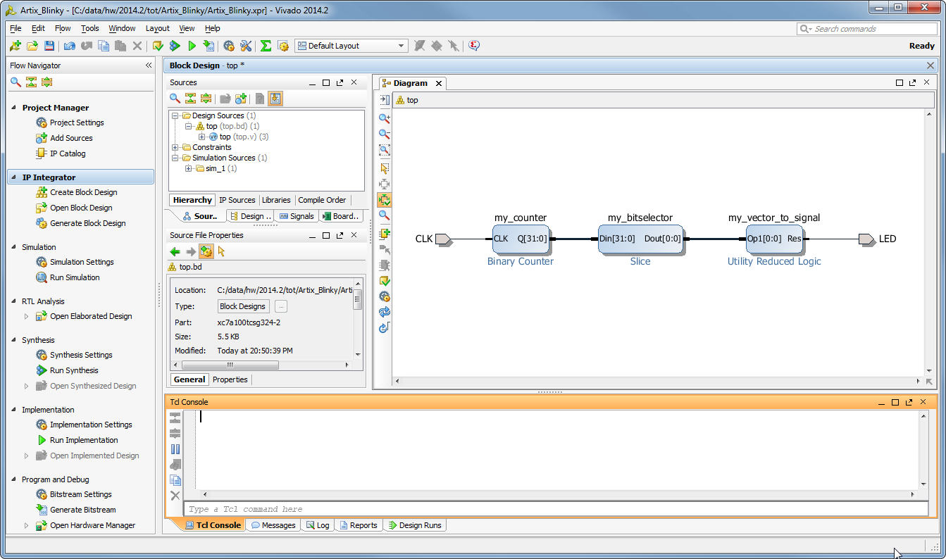
This is what we see after this TCL magic.
Next we create HDL Wrapper for the block desing (this could be done from the TCL as well).
Now we only need to assign the CLK and LED ports to proper FPGA pins, and we are ready to generate a bitfile that would blink a LED!
We can either assign the CLK and LED in the I/O Window that can be opened when we open elaborated design, or we can create a new constraint file, and execute a TCL script that well just writes the same constraints into the XDC ![]()
set_property package_pin A8 [get_ports LED]
set_property iostandard LVCMOS18 [get_ports [list LED]]
set_property package_pin F4 [get_ports CLK]
set_property iostandard LVCMOS15 [get_ports [list CLK]]
The above would set correct ports and I/O Standards to blink a LED on TE0710-01 Artix board. For any other target hardware the mappings would be different.
So simple it is.
To create Vivado projects that can be shared.
Does it work does it work does the LED blink?
As soon as I made this design I did write an email sharing the story, and said, well it is not tested on real hardware. But 3 minutes and 40 seconds later >>>
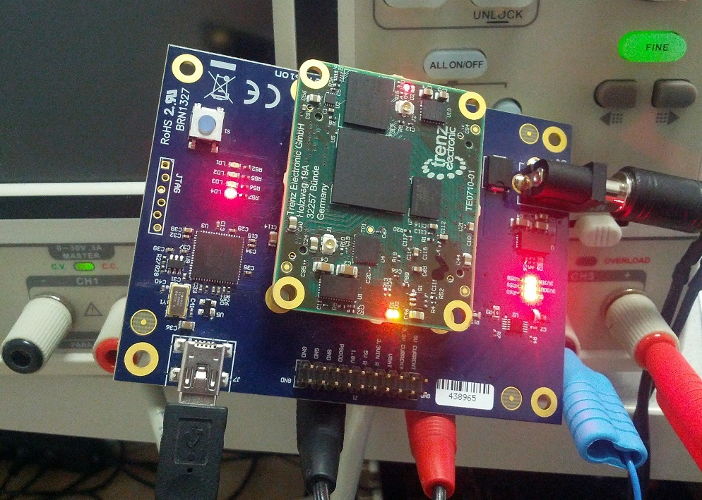
LED blink with TCL magic. There are actually 3 LED's blinking, the "Vivado TCL" LED is the red LED at the far top of TE0710.
At close bottom edge of TE0710 are red and green LED's, the green LED is also blinking (controlled by system controller on TE0710).
One LED on the TE0702 factory test baseboard is also blinking controlled by the base board controller.
But hey who did write this TCL?
I did not.
Vivado did, honestly. So Vivado can write it for you too. ![]() You just have to copy paste the proper lines of TCL from the TCL console output in Vivado.
You just have to copy paste the proper lines of TCL from the TCL console output in Vivado.
That's what I did.
And who created the Block Design?
Vivado did, it was not me, honestly.
Sure I had a second instance of Vivado open where I manually created the Block Design as primary design, and from where I copied the TCL log lines into text editor for manual post processing. But I really did not look up in any TCL guide or any other guide. I just looked what Vivado generated and used dumb copy paste method to make the TCL script to re-create the "Blinky" design. The Blinky bit file was then generated in the Vivado instance that used TCL script to create the design.
It all worked the first try.
Click, Click, and blink!
Overview
Content Tools