Page History
...
Preparation for test of CR00140 with Motor
Compare with picture in section 'Motor test - 3.' below.
- Connect 5V DC adapter to TEB0707 (J1)
- Connect Ethernet of TEB0707 (J2) (direct connection to PC, e.g. USB-ETH Adapter)
- Connect micro USB of TEB0707 (J15) to PC (Not needed for Test, but for debugging UART serial console)
- Connect Motor phases (J8 screw terminal)
- yellow → A
- red → B
- black → C
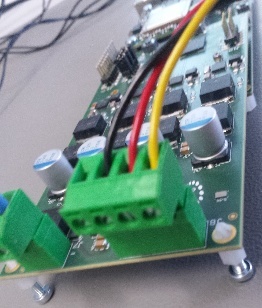
- Connect 24V on CR00140 (J7 screw terminal). Check polarity!
Connect motor-encoder via 5-pin encoder cable to J1 of CR00140. On both sides (Motor and CR00140) the brown wire is connected to pin 1.
...
- Power on TBE0707 (5V)
- check current: ~1.0A
check shortly after start Done LED goes of
TE0720 TE0820 green LED D4 red LED D1 - 3 red LEDs on TEB0707 go off after Linux startup. This indicates system ready for test.
- Power on CR00140 motor stage (24V)
- check current ~0.05A
- Press S1 on CR00140 (D1 on CR00140 should now blink)
The setup should look like this, (+cooler on Module)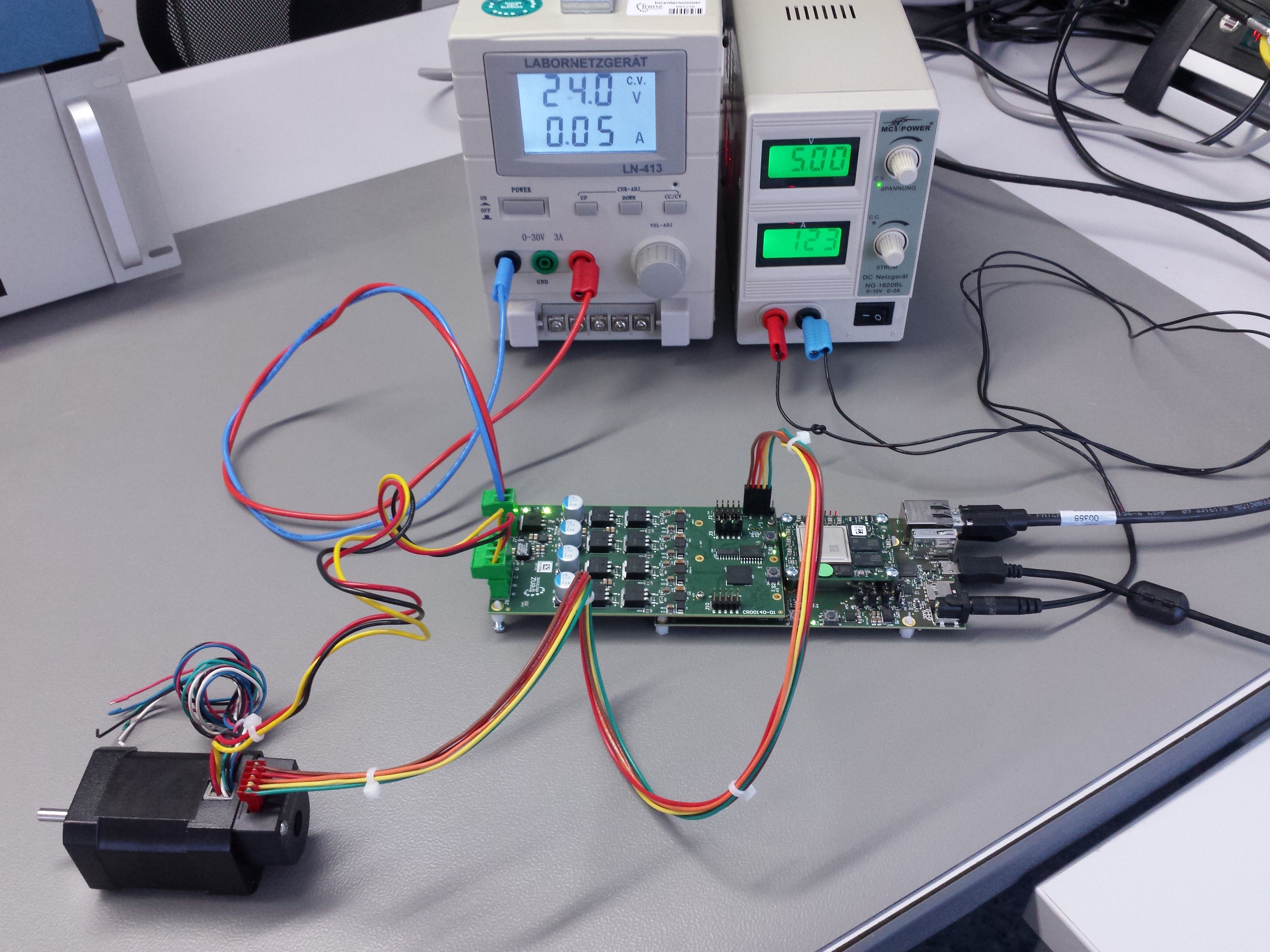
- Open saved Matlab project from above.
- t6_download Bitstream (module will automatically restart, no vivado HW manger should be connected, otherwise restart will fail.)
draw.io Diagram border falsetrue diagramName CR00140_MatLabMathworks_run_testbit simpleViewer false width links auto tbstyle top diagramDisplayNamelbox falsetrue diagramWidth 899 revision 1 Current consumption
TE0720 TE0820 ~0.8 A ~1.2 A - three red LEDs D4, D5, D6 on TEB0707 go off after peatlinux is up completely. (Can also be checked via UART console, e.g. use putty, Baut rate 115200)
- open t7_openZynqARMmodel
- If Scope window doesen't open automatically, double click on Scope
- Press Run
- Wait until motor demo has finished (1 minute +)
draw.io Diagram border falsetrue diagramName CR00140_test_mathworks simpleViewer false width 400links auto tbstyle top diagramDisplayName lbox falsetrue diagramWidth 12211220 revision 31
Overview
Content Tools