Develop, simulate and test of motor control algorithms with this modular motor kit is supported by MathWorks with hardware support packages for Matlab and Simulink (licence needed).
Content of the kit
The motor kit is availabe in two configurations with either a Zynq Ultrascale+ SoM (TE0820 in Kit CR00140-02-K0), or 7 series Zynq SoM (TE0720-03-1CFA in Kit CR00140-02-K1). The parts of the Motorkit are listed in the following table. The main components are linked to their general resources pages where detailed information like TRMs, schematic, firmware and firmeware description, assembly diagramms can be found.
For further insights see also the TRMs of each specific component:
| Components | Article number | Description |
|---|---|---|
| TEB0707 | TEB0707-02 | baseboard |
| CR00140 | CR00140-02 | motor driver board |
| TE0820 (option K0) or TE0720 (option K1) | TE0820-03-2AE21FA or TE0720-03-1CFA | SoM |
| BLY172D-24V-4000-1250SI | 30430 | motor with encoder |
| Included Accessories | ||
| micro SD Card | 26507 | 8GB SDHC |
| heat sink | 28606 or 26922 | (type depends on module) with assebly material (pre assembled) |
| 5V power supply | 28485 | for baseboard (barrel plug) |
| encoder cable | TEC0140-01-C | |
Additional accessories needed, not included:
| Components | Description |
|---|---|
| 24V power supply | with cables suitable for screw terminals |
| Ethernet cable | connection to development PC |
| micro USB cable | connection to development PC |
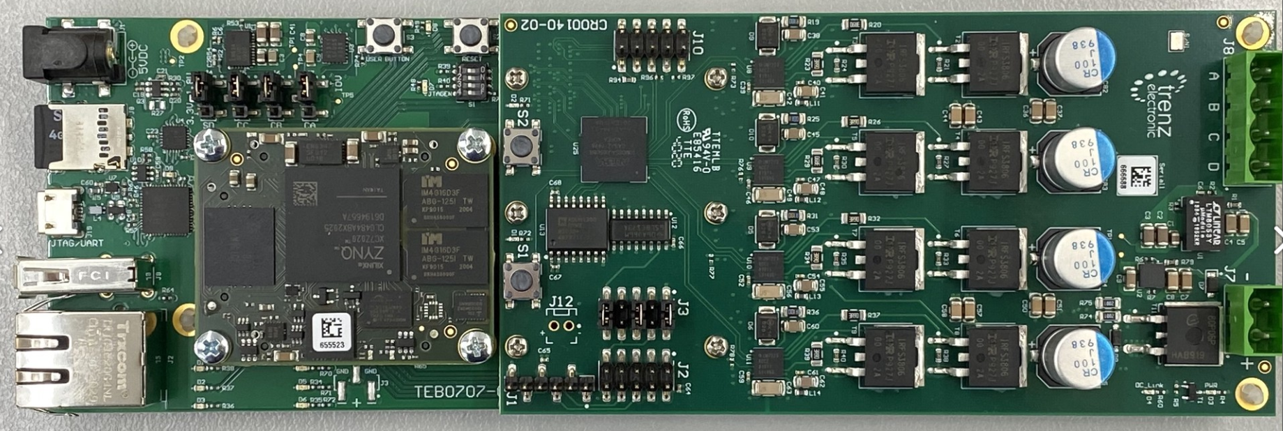
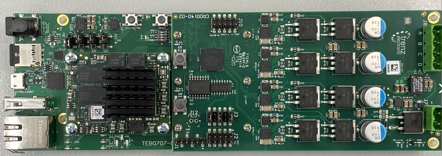
Preparation of CR00140 kit
Compare with picture below.
- Place FPGA Module (TE0820 or TE0720) with cooler on TEB0707
- Place CR00140 on TEB0707
- Jumper and Dip setting
Jumper setting on TEB0707:
J4: TE0820: SD→3.3V; TE0720: SD->1.8V
J5: CA → IOV,
J6: CB → IOV,
J7: CC → IOV- Dips on TEB0707: S1-1..4 all „OFF“
- CR00140 Jumper configuration for single ended encoder J3: 1-2, 5-6, 9-10
With TE0720
With TE0820
Preparation for test of CR00140 with Motor
Compare with picture in section 'Motor test - 3.' below.
- Connect 5V DC adapter to TEB0707 (J1)
- Connect Ethernet of TEB0707 (J2) (direct connection to PC, e.g. USB-ETH Adapter)
- Connect micro USB of TEB0707 (J15) to PC (Not needed for Test, but for debugging UART serial console)
- Connect Motor phases (J8 screw terminal)
- yellow → A
- red → B
- black → C
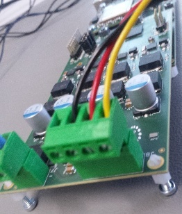
- Connect 24V on CR00140 (J7 screw terminal). Check polarity!
Connect motor-encoder via 5-pin encoder cable to J1 of CR00140. On both sides (Motor and CR00140) the brown wire is connected to pin 1.
Preparation of Software
Correct Vivado and MatLAB versions corresponding to the Mathworks motor control design are needed.
Copy all data of the corresponding Mathworks Motor control SD-image for TE0820 or TE0720 onto a SD-Card.
Place the SD-Card into TEB0707 (J8)
- Open Matlab
- check that following two AddOns are installed in actual version

check package setup for both packages (available via Matlab→ Home→ Add-Ons→ AddManage Add-Ons→ grey gear)
Select Hardware Board
TE0720 TE0820 Xilinx Zynq ZC702 evaluation kit Xilinx Zynq ultraScale+ MPSoC ZCU102 Evaluation kit 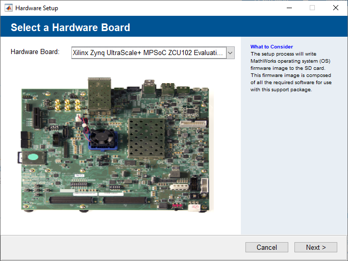
use option "Connect directly to development computer"
Set IP Address to 192.168.1.X (SoC has 192.168.1.101)
- register vivado version 20XX.X adding in file "~\Documents\MATLAB\startup.m":
hdlsetuptoolpath('ToolName','Xilinx Vivado','ToolPath','C:\Xilinx\Vivado\20XX.X\bin\vivado.bat')
if other directory is used for installation it has to be changed accordingly, replace X by used version of Mathworks design.
- check that following two AddOns are installed in actual version
- Open Mathworks motor control demo project for TE0820 or TE0720
- Ignore warning about path Work does not exist: OK→Continue
- open t4_open hdlWorkflowadvisor
select under 1.1 "Target platform" correct board:
Trenz TE0720 with CR00140 Trenz TE0820 with CR00140 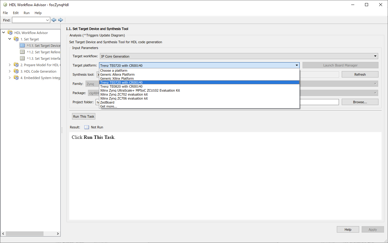
- Set Target and run all
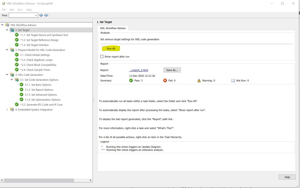
Do same (run all) for 2., 3.1, 3.2 (needs some time, press ok if window opens, will close automatically when finished)
run all tasks excluding 4.4
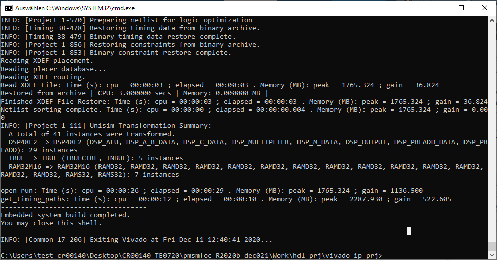
- 4.3 will need approx 10 minutes on an up to date desktop PC.
- close all Matlab windows and project (and save if asked)
- 4.3 will need approx 10 minutes on an up to date desktop PC.
Motor test
- Power on TBE0707 (5V)
- check current: ~1.0A
check shortly after start Done LED goes of
TE0720 TE0820 green LED D4 red LED D1 - 3 red LEDs on TEB0707 go off after Linux startup. This indicates system ready for test.
- Power on CR00140 motor stage (24V)
- check current ~0.05A
- Press push button S1 on CR00140 (D1 on CR00140 should now blink)
The setup should look like this, (+cooler on Module)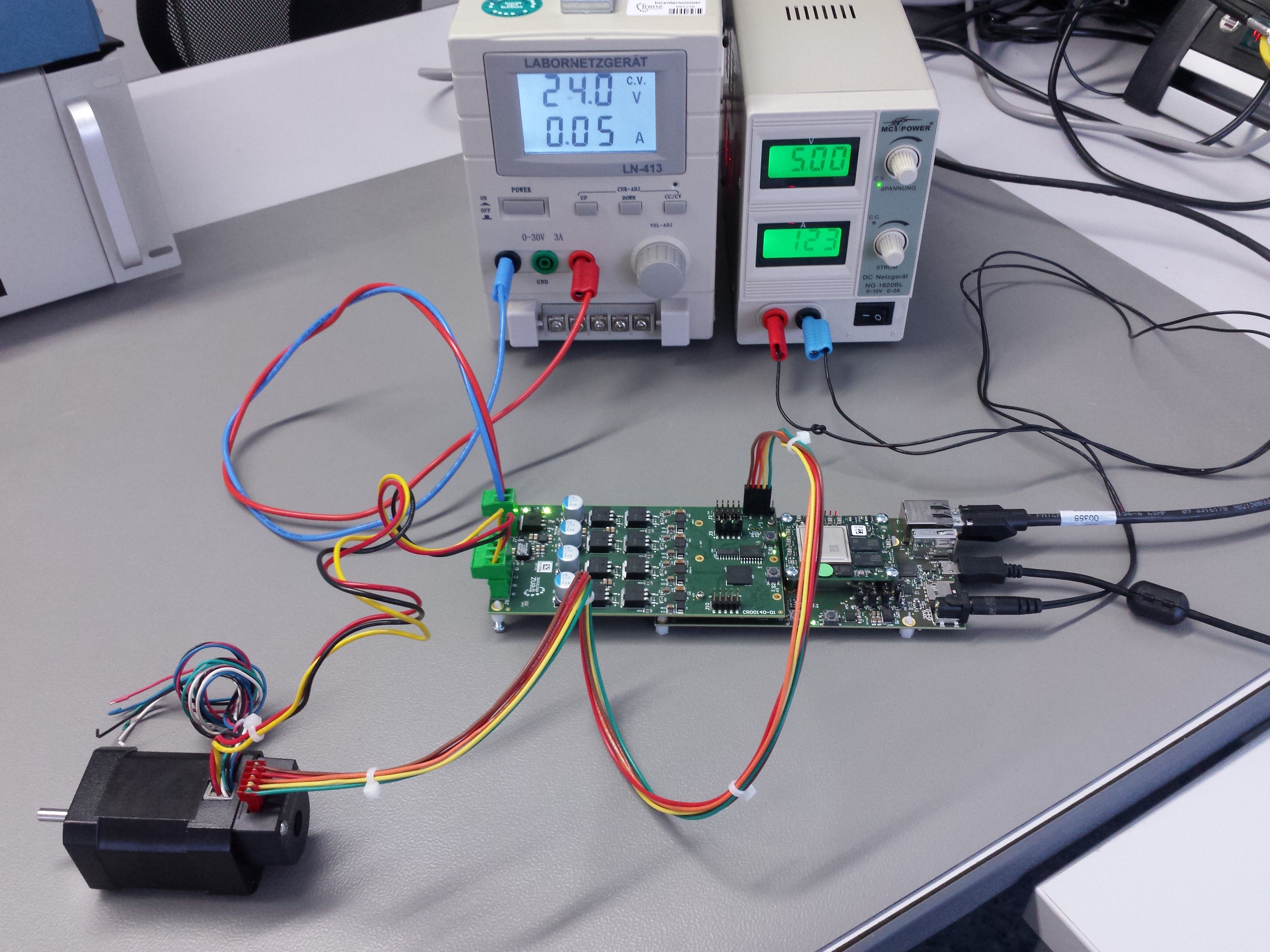
- Open saved Matlab project from above.
- t6_download Bitstream (module will automatically restart, no vivado HW manger should be connected, otherwise restart will fail.)
Current consumption
TE0720 TE0820 ~0.8 A ~1.2 A - three red LEDs D4, D5, D6 on TEB0707 go off after peatlinux is up completely. (Can also be checked via UART console, e.g. use putty, Baut rate 115200)
- open t7_openZynqARMmodel
- If Scope window doesen't open automatically, double click on Scope
- Press Run
- Wait until motor demo has finished (1 minute +)
Overview
Content Tools