Page History
| Scroll Ignore |
|---|
Download PDF Version of this Document. |
| Scroll pdf ignore | ||||
|---|---|---|---|---|
Table of Contents
|
Overview
| Scroll Only (inline) |
|---|
OnlineRefer to https://shop.trenz-electronic.de/de/Download/?path=Trenz_Electronic/carrier_boards/TE0703 for online version of this manual and other related documents canavailable beabout found at https://wiki.trenz-electronic.de/display/PD/TE0703the product. |
The Trenz Electronic TE0703 Carrier Board is a base-board for 4x5 SoMs, which exposes the MIO- and the PS/PL-pins of the SoM to accessible connectors and provides a whole range of on-board-components to test and evaluate Trenz Electronic 4x5 SoMs.
...
| Switch | ON | OFF |
|---|---|---|
| S2-1 | User configurable, routed to CPLD | User configurable, routed to CPLD |
| S2-2 | User configurable, routed to CPLD | User configurable, routed to CPLD |
| S2-3 | JTAG enabled for B2B connector JB2 | JTAG enabled for CPLD |
| S2-4 | Boot from SD Card | Boot from QSPI flash on module |
Power and Power-On Sequence
Power Supply
Power supply with minimum current capability of 3 A 3A for system startup is recommended.
...
Typical value: TE0703-05 + TE0715-01 module. SD micro card inserted. Ethernet connected, link up. System booted into Linux prompt and idling. Average power consumption was 5 V 5V / 0.55 A55A.
VCCIO voltage selection jumpers J5, J8, J9 and J10
Refer to the 4x5 Module Integration Guide for VCCIO voltage options.
If you choose to power IO banks
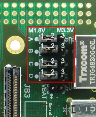
Jumper J5 | 1-2 | 2-3 | Voltage |
|---|---|---|---|
VCCIOA | ON | OFF | 1.8 V |
| VCCIOA | OFF | ON | 3.3 V |
...
42g - Plain board
13g - VG96 connector x 2
Document Change History
...
Date
...
Rrevision
...
Contributors
...
Description
...
V.01
...
Revision History
Hardware Revision History
Date | Revision | Notes | PCN |
|---|---|---|---|
- | 01 | Prototypes | - |
- | 02 | First series boards | - |
- | 03 | Added VCCIO strapping resistors | - |
- | 04 | Corrected FTDI EEPROM connection | - |
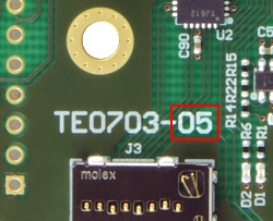
07.09.2016 | 05 | Added VCCIO Jumpers |
Hardware revision number is printed on the PCB board next to the module model number separated by the dash.
Document Change History
Date | Rrevision | Contributors | Description |
|---|---|---|---|
| 08.12.2016 | Jan Kumann | Document structure revised. | |
| 05.12.2016 |
| John Hartfiel | Corrected Boot Mode Table |
| 06.09.2016 | V.01 | Recreation |
Disclaimer
| Include Page | ||||
|---|---|---|---|---|
|
Overview
Content Tools