Page History
...
This header has a 'XMOD FTDI JTAG Adapter'-compatible pin-assignment, so the XMOD-FT2232H adapter-board TE0790 can be used in conjunction with the carried board Carrier Board to program the mounted SoM via USB interface.
...
| Note |
|---|
Note: The corresponding PL IO-voltage supply voltages of the 4x5 SoM to the selectable base-board voltage VCCIOA and VCCIOD are depending on the mounted 4x5 SoM and varying in order of the used model. Refer to SoM's schematic to get information about the specific pin-assignment on module's B2B-connectors regarding PL IO-bank supply-voltages and to the 4x5 Module integration Guide for VCCIO voltage options. |
Following table describes how to configure the base-board supply-voltages by jumpers:
Base-board Supply Voltages | VCCIOA | VCCIOD |
|---|---|---|
| 1.8V | J26:1-2 | J27:1-2 |
| 2.5V | J26:3-4 | J27:3-4 |
| 3.3V | J26:5-6 | J27:5-6 |
Table 6: Configuration of base-board supply-voltages via jumpers. Jumper-Notification: 'Jx: 1-2' means pins 1 and 2 are connected, 'Jx: 3-4' means pins 3 and 4 are connected, and so on.
| Note |
|---|
Take care of the VCCO voltage ranges of the particular PL IO-banks (HR, HP) of the mounted SoM, otherwise damages may occur to the FPGA. Therefore, refer to the TRM of the mounted SoM to get the specific information of the voltage ranges. It is recommended to set and measure the PL IO-bank supply-voltages before mounting of TE 4x54 x 5 module to avoid failures and damages to the functionality of the mounted SoM. |
Technical Specifications
Absolute Maximum Ratings
...
Weight
ca. 32 g - Plain board
Hardware Revision History
| Date | Revision | Notes | PCN | Documentation link |
|---|---|---|---|---|
| - | 01 | - | - | - |
Hardware revision number is printed on the PCB board next to the model number separated by the dash.
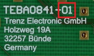
Figure 5: Hardware revision Number
Document Change History
| Date | Revision | Authors | Description |
|---|---|---|---|
| 2017- |
| 06- |
| 08 | Ali Naseri | current TRM for TEBA0841-01 | |
| 2017-01-30 | 0.1 | Ali Naseri | Initial document |
Hardware Revision History
| Date | Revision | Notes | PCN | Documentation link |
|---|---|---|---|---|
| - | 01 |
...
Hardware revision number is printed on the PCB board next to the model number separated by the dash.
Disclaimer
| Include Page | ||||
|---|---|---|---|---|
|
Overview
Content Tools