Page History
...
| Note |
|---|
None of the EDDP components is intended to be used in finished products, all the software and hardware parts of the Platform are intended for Developers evaluating Motor Control Applications with Xilinx FPGA and or SoC Devices. |
EDPS Drive Board TEC0053
Option 1: with DC +12V Reference Motor Board (Delivery condition)
...
| Detail | Option 1: Reference Motor Board with DC +12V Supply | Option 2: Customer Motor at individual DC +5..48V | Comment |
|---|---|---|---|
| Motor Supply | From DC +12V Input J7 via Fuse F3 (TODO ... A) | From customer DC Supply to J6 via F1 on Eval Boad | |
| Motor Connection | Motor wires connected to cage clamps on Motor Reference Board J5 (A), J4 (B), J3 (C) | Motor wires connected to bolt screw terminals on Eval Board J2 (A), J3 (B), J4 (C) | |
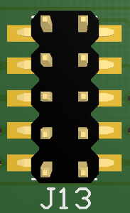
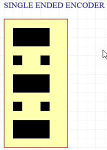
| Encoder Connection | From encoder pins via ribbon cable to Eval Board J10, 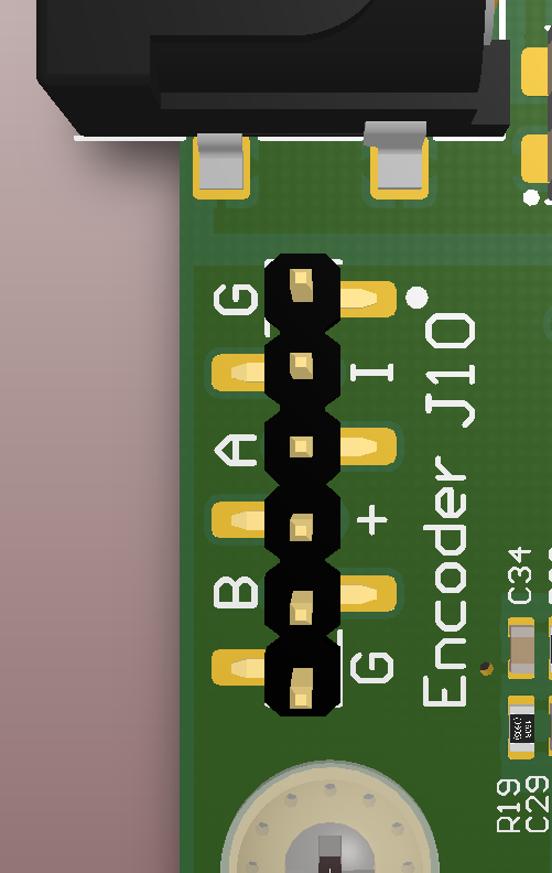 J11 single ended: | From motor to Eval Board J10 (only single ende signals) see left colomn, or to J11 (single OR differential signals): 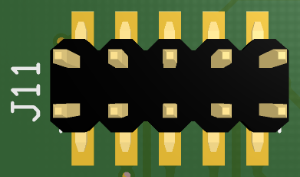 J11 single ended: J11 differential with 100R terminated: | Jumper Settings for encoder signals.
|
Reference Motor Board TEC0060
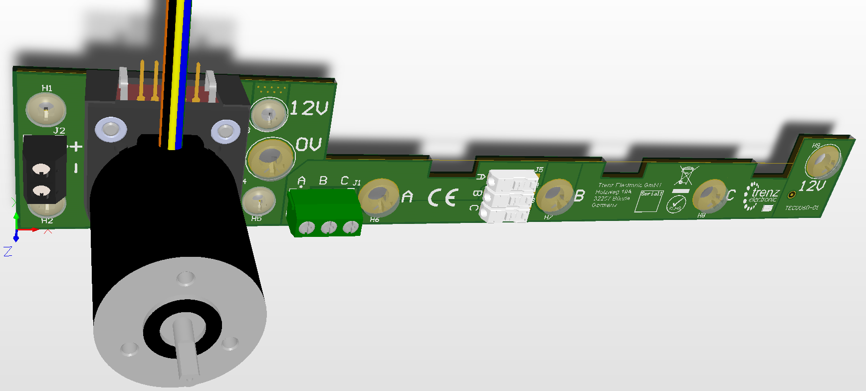
Reference Motor
The manufaturer of the reference motor is Anaheim Automation and the order code of the delivered combination of the motor with encoder is BLWR111D-24V-10000-1000SI. Please not the encoder is not available separatly, they are premounted to the motor at the manufacturer.
The nominal motor voltage is DC 24V which is supplied by DC 12V on the Reference Motor Board. This will cause a certain derating in performace.
...
Overview
Content Tools