Page History
...
Green LED D4 (C_LED) connected to the System Controller CPLD is to indicate the status of the module.
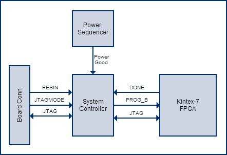
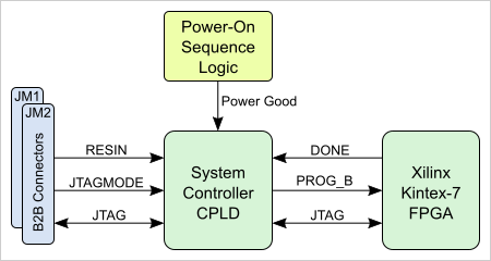
Figure 5: System Controller block diagram.
...
| Date | Revision | Contributors | Description | ||||||||
|---|---|---|---|---|---|---|---|---|---|---|---|
| Jan Kumann | New power-on diagram. Few improvements. Template revision added. | |||||||||
| 2017-07-20 | v.57 | John Hartfiel | Correction: PLL default output CLKs. | ||||||||
| 2017-06-07 | v.55 | Jan Kumann | Minor formatting | ||||||||
| 2017-06-02 | v.50 | Jan Kumann | REV03 specific update. | ||||||||
| 2017-01-22 | v.42 | Jan Kumann | New block diagram added. | ||||||||
| 2017-01-13 | v.38 | Jan Kumann | New product images and physical dimension drawings. Formatting improvements and small corrections. | ||||||||
| 2017-01-12 | v.21 | John Hartfiel | Correction: B2B and FPGA bank location. | ||||||||
| 2016-12-14 | v.19 | Ali Naseri | TRM revision. | ||||||||
| 2013-12-02 | v.1 | Antti Lukats, Jon Bean | Initial version. |
...
Overview
Content Tools