Page History
...
| Date | Vivado | Project Built | Authors | Description |
|---|---|---|---|---|
| 2017-09-22 | 2017.2 | te0715-test_board-vivado_2017.2-build_02_2017092213183720170927084628.zip te0715-test_board_noprebuilt-vivado_2017.2-build_02_2017092213185320170927084641.zip | John Hartfiel | initial release |
...
Design supports following modulescarriers:
| Carrier Model | Notes |
|---|---|
| TE0701 | |
| TE0703 | |
| TE0705 | |
| TE0706 | used as reference carrier |
| TEBA0841 |
Additional HW Requirements:
| Additional Hardware | Notes |
|---|---|
| USB Cable for JTAG/UART | Check Carrier Board and Programmer for correct typ |
| XMOD Programmer | Carrier Board dependent, only if carrier has no own FTDI |
...
Reference Design is available on:
Design Flow
| HTML |
|---|
<!-- Basic Design Steps Add/ Remove project specific --> |
| Note |
|---|
Reference Design is also available with and without prebuilt files. It's recommended to use TE prebuilt files for first lunch. |
...
Trenz Electronic provides a tcl based built environment based on Xilinx Design Flow.
See also:Vivado/SDK/SDSoC#XilinxSoftware-BasicUserGuides and /SDSoC
The most Trenz Electronic FPGA Reference Designs are TCL-script based project. Command files for execution will be generated with "_create_win_setup.cmd" on Windows OS and "_create_linux_setup.sh" on Linux OS.
TE Scripts are only needed to generate the vivado project, all other additional steps are optional and can also executed by Xilinx Vivado/SDK GUI. For currently Scripts limitations on Win and Linux OS see: Project Delivery Currently limitations of functionality
...
- Run _create_win_setup.cmd/_create_linux_setup.sh and follow instructions on shell:
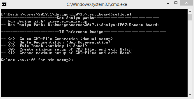
- Press 0 and enter for minimum setup
- (optional Win OS) Generate Virtual Drive or use short directory for the reference design (for example x:\<design name>)
- Create Project
- Select correct device and Xilinx install path on "design_basic_settings.cmd" and create Vivado project with "vivado_create_project_guimode.cmd"
Note: Select correct one, see TE Board Part Files
- Select correct device and Xilinx install path on "design_basic_settings.cmd" and create Vivado project with "vivado_create_project_guimode.cmd"
- Create HDF and export to prebuilt folder
- Run on Vivado TCL: TE::hw_build_design -export_prebuilt
Note: Script generate design and export files into \prebuilt\hardware\<short dir>. Use GUI is the same, except file export to prebuilt folder
- Run on Vivado TCL: TE::hw_build_design -export_prebuilt
- Create Linux (uboot.elf and image.ub) with exported HDF
- HDF is exported to "prebuilt\hardware\<short name>"
Note: HW Export from Vivado GUI used default create another path as default workspace. - Create Linux images on VM, see PetaLinux KICKstart
- Use TE Template from /os/petalinux
- HDF is exported to "prebuilt\hardware\<short name>"
- Add Linux files (uboot.elf and image.ub) to prebuilt folder
- "prebuilt\os\petalinux\default" or "prebuilt\os\petalinux\<short name>"
Notes: Scrips Scripts select "prebuilt\os\petalinux\<short name>", if exist, otherwise "prebuilt\os\petalinux\default"
- "prebuilt\os\petalinux\default" or "prebuilt\os\petalinux\<short name>"
- Generate Programming Files with HSI/SDK
- Run on Vivado TCL: TE::sw_run_hsi
Note: Scripts generate applications and bootable files, which are defined in "sw_lib\apps_list.csv" - (alternative) Use start Start SDK with Vivado GUI or start with TE Scripts on Vivado TCL: TE::sw_run_sdk
Note: See SDK Projects
- Run on Vivado TCL: TE::sw_run_hsi
...
- Prepare HW like described on section programming Programming
- Connect UART USB (most cases same as JTAG)
- Power On PCB
Linux
- Select SD Card as Boot Mode
Note: See TRM of the Carrier, which is used. - Power On PCB
Note: 1. Zynq Boot ROM loads FSBL from SD into OCM, 2. FSBL loads U-boot from SD into DDR, 3. U-boot load Linux from SD into DDR
Linux
- Open Serial Console (e.g. putty)
- Speed: 115200
- COM Port: Win OS, see device manager
- Speed: 115200
- COM Port: Win OS, see device manager, Linux OS see dmesg |grep tty (UART is *USB1)
- Linux Console:
- User Name: root
- Password: root Note: Wait until Linux boot finished For Linux Login use:
- User Name: root
- Password: root
- You can use Linux shell now.
Vivado HW Manager
MGT Reference CLK Counter:
...
| HTML |
|---|
<!-- Description of Block Design, Constrains... BD Pictures from Export... --> |
...
Description currently not available.
Block Design
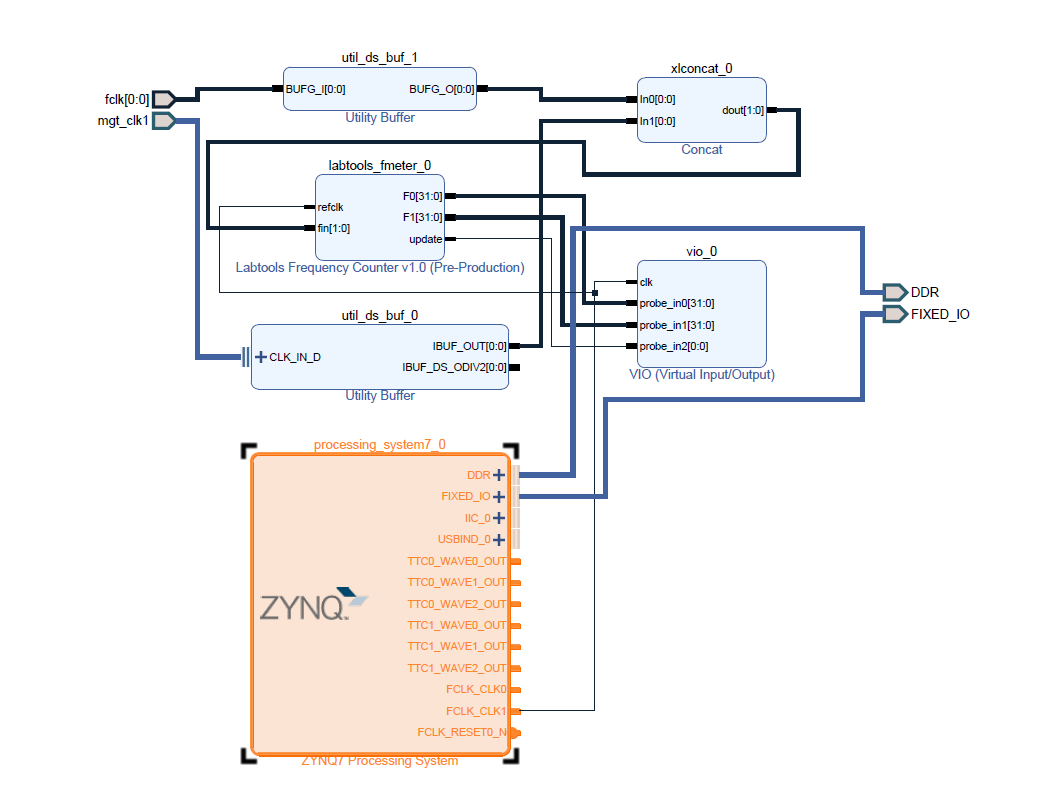
PS Interfaces
Activated interfaces:
| Type | Note |
|---|---|
| DDR | --- |
| QSPI | MIO |
| I2C0 | EMIO- NC |
| I2C1 | MIO |
| UART0 | MIO |
| GPIO | MIO |
| SD0 | MIO |
| USB0 | MIO |
| ETH0 | MIO |
| TTC | EMIO |
Constrains
Basic module constrains
...
Overview
Content Tools