Page History
...
The Adapter Board is mounted to the EDPS Board using 5 x M6 screws (Labels 0V, A, B, C, 12V on Adapter Board) and with M3 screws and spacer - marked 12V at the left. This Adapter board Board "forwards" (the yellow arrow) the EDPS Board pre-driver supply (12V) to the DC Link main terminal on the EDPS board, so that separate DC Link power supply is not needed allowing easy evaluation of the complete system.
...
Note terminal marked+DC must be left open when using the Adapter boardBoard!
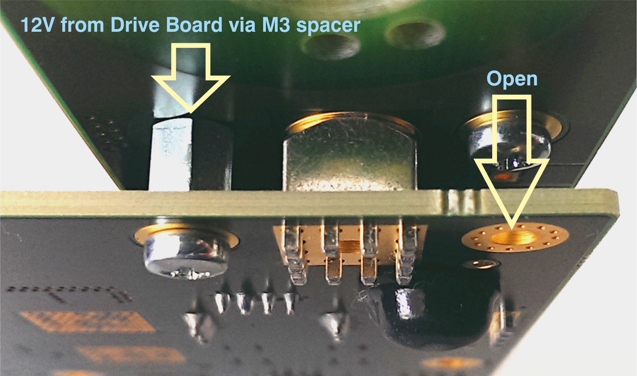
Figure 2: M3 spacer and two M3 screws connect 12V from the EDPS board to the Adapter boardBoard.
Motor Connection
In the EDDP Kit the Reference Motor stator wires for all three phases are already connected to the Adapter Board. Instructions for manual assembly below:
...
A 3-phase permanent-magnet synchronous motor with attached encoder and mechanical load is mounted to a EDPS Board by using an Adapter Board. The EDPS Board is connected to a Control Board ARTY-Z7 through PMOD connectors. A Host PC running a Web Browser connects to the Control Board through a Network.
...
Overview
Content Tools