Page History
...
- Xmod form-factor
- size: 20 x 25 mm
- M3 mounting hole
- FT2232H
- USB2.0 port High Speed (480 Mbps) and Full Speed (12 Mbps) compatible
- Entire USB protocol handled on the chip
- USB2.0 to JTAG, SPI and I²C conversion provided by the IC's Multi-Protocol Synchronous Serial Engine (MPSSE)
- USB2.0 to UART conversion
- Channel B UART RX/TX LED's
- Mini-USB B connector (more rigid then micro-USB)
- 93C56 EEPROM
- Lattice XO2-256 CPLD
- on board programmable using Lattice tools
- 8 universal I/O pins
- VCCIO either 3.3V or user supplied (1.8 to 3.3V)
- RED user LED
- 12 MHz clock from on-board Oscillator
- Variable power supply of the XMOD adapter board
- by Mini USB2.0 connector
- by base-board through pin header J2
- GREEN Power-on LED
- User button
- 4 position DIP switch
- Choose CPLD program mode
- FTDI EEPROM disable (not implemented in PCB REV 1)
- Use VIO same as VCC
- Use VCC from USB
Block Diagram
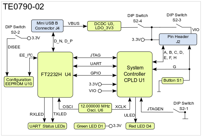
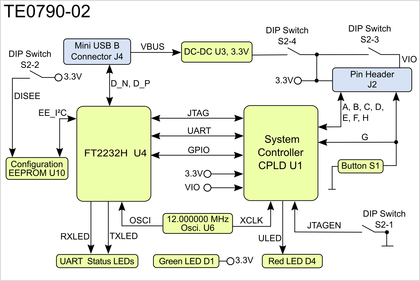
Figure 1: TE0790-02 block diagram.
...
The adapter on-board's peripherals are powered with 3.3V as supply voltage. If 3.3V and VIO is supplied only by the on-board LDO DCDC converter U3 (switches S2-3 and S2-4 ON), the I/O-pins of header J2 deliver max. XMOD adapter board has max. output current of ~100mA.
If module is powered from base then S2-4 (and most likely S2-3 (VIO) too) must be OFF.
Following diagram shows how the settings of the DIP-switches S2-3 and S2-4 determines the configuration of the on-board voltages:
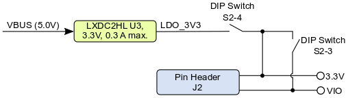

Figure 4: TE0790 on-board voltages configuration
...
Date | Revision | Contributors | Description | ||||||||
|---|---|---|---|---|---|---|---|---|---|---|---|
| Ali Naseri |
| |||||||||
2017-10-26 | v.27 | John Hartfiel |
| ||||||||
| 2017-10-19 | v.26 | Ali Naseri |
|
...
| Include Page | ||||
|---|---|---|---|---|
|
Overview
Content Tools