Page History
...
| HTML |
|---|
<!-- - Add changes from design - Export PDF to download, if vivado revision is changed! --> |
| Date | Vivado | Project Built | Authors | Description |
|---|---|---|---|---|
| 2017- |
| 11- |
| 28 | 2017.2 |
| TEF1001-test_board-vivado_2017.2-build_05_20171128114335.zip TEF1001-test_board_noprebuilt-vivado_2017. |
| 2-build_05_ |
| 20171128114350.zip | John Hartfiel | initial release |
Release Notes and Know Issues
| HTML |
|---|
<!-- - add known Design issues and general Notes for the current revision --> |
| Issues | Description | Workaround | To be fixed version |
|---|---|---|---|
| No known issues | --- | --- | --- |
Requirements
Software
| HTML |
|---|
<!-- Add needed external Software --> |
| Software | Version | Note |
|---|---|---|
| Vivado | 2017.2 | needed |
| SDK | 2017.2 | needed |
| SI5338 Clock Builder | --- | optional |
Hardware
| HTML |
|---|
<!-- Hardware Support --> |
...
Design supports following modules:
| Module Model | Board Part Short Name | PCB Revision Support | DDR | QSPI Flash | Others | Notes |
|---|
| TEF1001-01 | 160_2 | REV01 | SODIMM | 32MB | Set correct DDR settings on MIG |
Design supports following carriers:
| Carrier Model | Notes |
|---|
| PC with PCIe Card slot |
Additional HW Requirements:
| Additional Hardware | Notes |
|---|
| JTAG Programmer | TE0790 with TE0791 or other Programmer |
Content
| HTML |
|---|
<!-- Remove unused content --> |
For general structure and of the reference design, see Project Delivery
Design Sources
| Type | Location | Notes |
|---|---|---|
| Vivado | <design name>/block_design <design name>/constraints <design name>/ip_lib | Vivado Project will be generated by TE Scripts |
| SDK/HSI | <design name>/sw_lib | Additional Software Template for SDK/HSI and apps_list.csv with settings for HSI |
Additional Sources
| Type | Location | Notes |
|---|
| SI5338 | <design name>/misc/Si5338 |
| SI5338 Project with current PLL Configuration |
Prebuilt
Prebuilt
| HTML |
|---|
<!-- <table width="100%"> <tr> <th>File </th> <th>File-Extension</th> <th>Description </th> </tr> <tr> <td>BIF-File </td> <td>*.bif </td> <td>File with description to generate Bin-File </td> </tr> <tr> <td>BIN-File </td> <td>*.bin </td> <td>Flash Configuration File with Boot-Image (Zynq-FPGAs) </td> </tr> <tr> <td>BIT-File </td> <td>*.bit </td> <td>FPGA Configuration File </td> </tr> <tr> <td>DebugProbes-File </td> <td>*.ltx </td> <td>Definition File for Vivado/Vivado Labtools Debugging Interface </td> </tr> <tr> <td>Debian SD-Image </td> <td>*.img </td> <td>Debian Image for SD-Card </td> </tr> <tr> <td>Diverse Reports </td> <td> --- </td> <td>Report files in different formats </td> </tr> <tr> <td>Hardware-Platform-Specification-Files</td> <td>*.hdf </td> <td>Exported Vivado Hardware Specification for SDK/HSI </td> </tr> <tr> <td>LabTools Project-File </td> <td>*.lpr </td> <td>Vivado Labtools Project File </td> </tr> <tr> <td>MCS-File </td> <td>*.mcs </td> <td>Flash Configuration File with Boot-Image (MicroBlaze or FPGA part only) </td> </tr> <tr> <td>MMI-File </td> <td>*.mmi </td> <td>File with BRAM-Location to generate MCS or BIT-File with *.elf content (MicroBlaze only) </td> </tr> <tr> <td>OS-Image </td> <td>*.ub </td> <td>Image with Linux Kernel (On Petalinux optional with Devicetree and RAM-Disk) </td> </tr> <tr> <td>Software-Application-File </td> <td>*.elf </td> <td>Software Application for Zynq or MicroBlaze Processor Systems </td> </tr> <tr> <td>SREC-File </td> <td>*.srec </td> <td>Converted Software Application for MicroBlaze Processor Systems </td> </tr> </table> --> |
File | File-Extension | Description |
|---|
| BIT-File | *.bit | FPGA (PL Part) Configuration File |
| DebugProbes-File | *.ltx | Definition File for Vivado/Vivado Labtools Debugging Interface |
*.img
Debian Image for SD-Card
| Diverse Reports | --- | Report files in different formats |
| Hardware-Platform-Specification-Files | *.hdf | Exported Vivado Hardware Specification for SDK/HSI and PetaLinux |
| LabTools Project-File | *.lpr | Vivado Labtools Project File |
MCS-File | *.mcs | Flash Configuration File with Boot-Image (MicroBlaze or FPGA part only) |
MMI-File | *.mmi | File with BRAM-Location to generate MCS or BIT-File with *.elf content (MicroBlaze only) |
| Software-Application-File | *.elf | Software Application for Zynq or MicroBlaze Processor Systems |
SREC-File
*.srec
Converted Software Application for MicroBlaze Processor Systems
Download
Reference Design is only usable with the specified Vivado/SDK/PetaLinux/SDx version. Do never use different Versions of Xilinx Software for the same Project.
...
Reference Design is available on:
- TE0??? TEF1001 "Test Board" Reference Design Download Area
Design Flow
| HTML |
|---|
<!-- Basic Design Steps Add/ Remove project specific --> |
...
- _create_win_setup.cmd/_create_linux_setup.sh and follow instructions on shell:
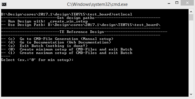
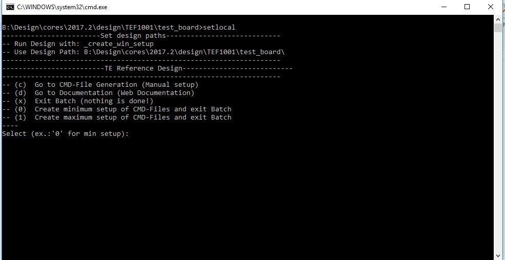
- Press 0 and enter for minimum setup
- (optional Win OS) Generate Virtual Drive or use short directory for the reference design (for example x:\<design name>)
- Create Project
- Select correct device and Xilinx install path on "design_basic_settings.cmd" and create Vivado project with "vivado_create_project_guimode.cmd"
Note: Select correct one, see TE Board Part Files
- Select correct device and Xilinx install path on "design_basic_settings.cmd" and create Vivado project with "vivado_create_project_guimode.cmd"
- Create HDF and export to prebuilt folder
- Run on Vivado TCL: TE::hw_build_design -export_prebuilt
Note: Script generate design and export files into \prebuilt\hardware\<short dir>. Use GUI is the same, except file export to prebuilt folder
- Run on Vivado TCL: TE::hw_build_design -export_prebuilt
- Create Linux (uboot.elf and image.ub) with exported HDF
- HDF is exported to "prebuilt\hardware\<short name>"
Note: HW Export from Vivado GUI create another path as default workspace. - Create Linux images on VM, see PetaLinux KICKstart
- Use TE Template from /os/petalinux
Note: run init_config.sh before you start petalinux config. This will set correct temporary path variable.
- Use TE Template from /os/petalinux
- HDF is exported to "prebuilt\hardware\<short name>"
- Add Linux files (uboot.elf and image.ub) to prebuilt folder
- "prebuilt\os\petalinux\default" or "prebuilt\os\petalinux\<short name>"
Notes: Scripts select "prebuilt\os\petalinux\<short name>", if exist, otherwise "prebuilt\os\petalinux\default"
- "prebuilt\os\petalinux\default" or "prebuilt\os\petalinux\<short name>"
- Generate Programming Files with HSI/SDK
- Run on Vivado TCL: TE::sw_run_hsi
Note: Scripts generate applications and bootable files, which are defined in "sw_lib\apps_list.csv" - (alternative) Start SDK with Vivado GUI or start with TE Scripts on Vivado TCL: TE::sw_run_sdk
Note: See SDK Projects
- Run on Vivado TCL: TE::sw_run_hsi
SDSoC (only tested on Win OS)
- Generate Platform Project or use prebuilt from download
- ...
Launch
Programming
- Generate Programming Files with HSI/SDK
- Start SDK with Vivado GUI or start with TE Scripts on Vivado TCL: TE::sw_run_sdk
Note: See SDK Projects - Create SI5338 Firmware Example project
- (only without DDR on SODIMM) Change Linker Script to BlockRAM (lscript.ld)
- Regenerate Design
- Start SDK with Vivado GUI or start with TE Scripts on Vivado TCL: TE::sw_run_sdk
- (optional Block RAM Update) Copy SI5338.elf into "test_board\firmware\microblaze_0" and regenerate Design with TE::hw_build_design -export_prebuilt
Launch
Programming
| HTML |
|---|
<!--
Description of Block Design, Constrains...
BD Pictures from Export...
|
| HTML |
<!--
Description of Block Design, Constrains...
BD Pictures from Export...
--> |
| Note |
|---|
Check Module and Carrier TRMs for proper HW configuration before you try any design. |
Xilinx documentation for programming and debugging: Vivado/SDK/SDSoC-Xilinx Software Programming and Debugging
QSPI
Not used on this Example.
...
- Connect
...
- JTAG and Power ON PC
- Open Vivado HW Manager with: TE::pr_init_hardware_manager
- Select generated mcs and prm file: test_board/prebuilt/hardware/<assembly option>/ and test_board/prebuilt/hardware/<assembly option>/reports/
- Configure Flash
- Reboot PC
| HTML |
|---|
<!-- Example: Connect JTAG and power on PCB (if and power on PCB (if not done) Select correct device and Xilinx install path on "design_basic_settings.cmd" and create Vivado project with "vivado_create_project_guimode.cmd" or open with "vivado_open_project_guimode.cmd", if generated. Type on Vivado Console: TE::pr_program_flash_mcsfile -swapp u-boot Note: Alternative use SDK or setup Flash on Vivado manually Reboot (if not done automatically) --> |
SD
- Copy image.ub and Boot.bin on SD-Card.
- For correct prebuilt file location, see <design_name>/prebuilt/readme_file_location.txt
- Set Boot Mode to SD-Boot.
- Depends on Carrier, see carrier TRM.
- Insert SD-Card in SD-Slot.
Not used on this Example.
JTAG
Not used on this Example.
...
- Prepare HW like described on section Programming
- Connect UART USB (most cases same as JTAG)
- Select SD Card as Boot Mode
Note: See TRM of the Carrier, which is used. - Power On PCB
Note: 1. Zynq Boot ROM loads FSBL from SD into OCM, 2. FSBL loads U-boot from SD into DDR, 3. U-boot load Linux from SD into DDR
Linux
- Open Serial Console (e.g. putty)
- Speed: 115200
- COM Port: Win OS, see device manager, Linux OS see dmesg |grep tty (UART is *USB1)
- Linux Console:
Note: Wait until Linux boot finished For Linux Login use:- User Name: root
- Password: root
- Power On PCB
Note: 1. Artix Load Bitfile (optional with SI5338 Initialisation App) into FPGA
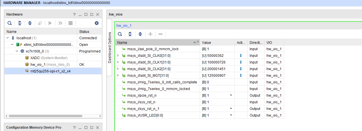
Vivado HW Manager
- Open Vivado HW Manager
- Add VIO to Dashboard:
- Set Radix to unsigned integer for FMeterCLKs
- Control:
- USER LED is selectable
- Optional PCIe Core Reset (on FPGA only)
- Optional System Reset (on FPGA only)
- Read: All SI5338 CLKs (Unit Hz), PCIe Cor MMCM Lock signal, MIG MMCM Lock signal, MIG Init Calibration
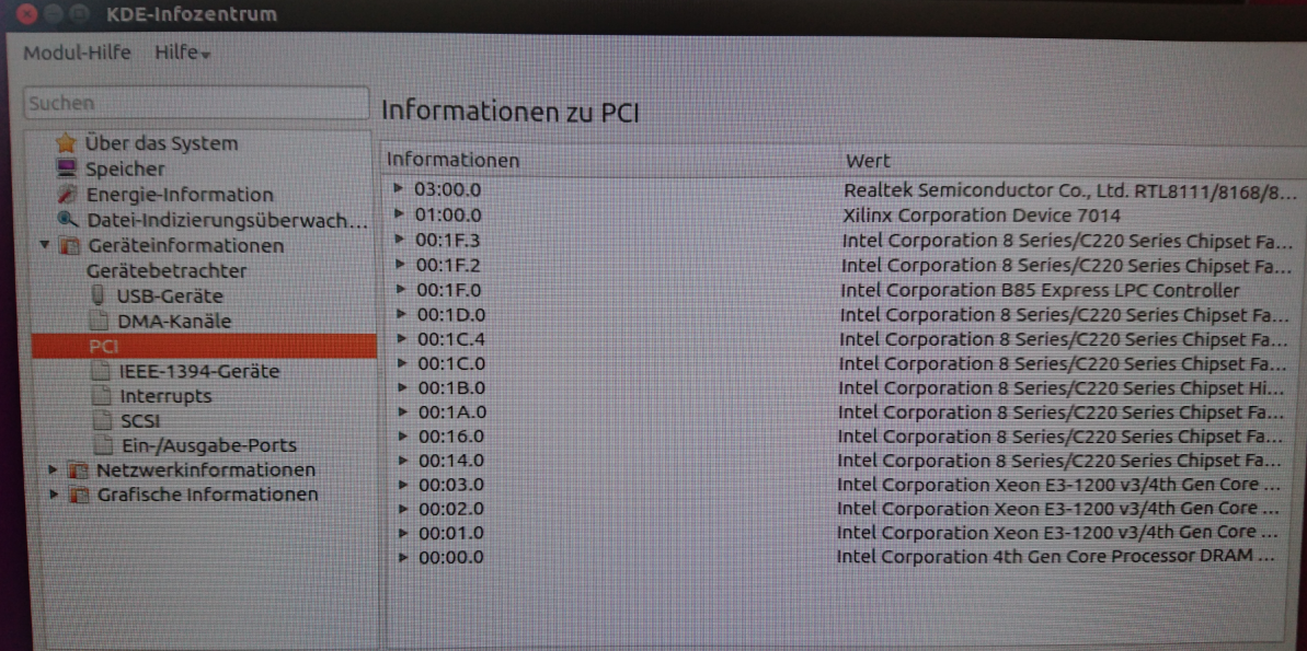
PC
Use for example PCI-Z (Win) or KInfoCenter (Linux) to detect PCIe Card
System Design - Vivado
| HTML |
|---|
<!-- Description of Block Design, Constrains... BD Pictures from Export... --> |
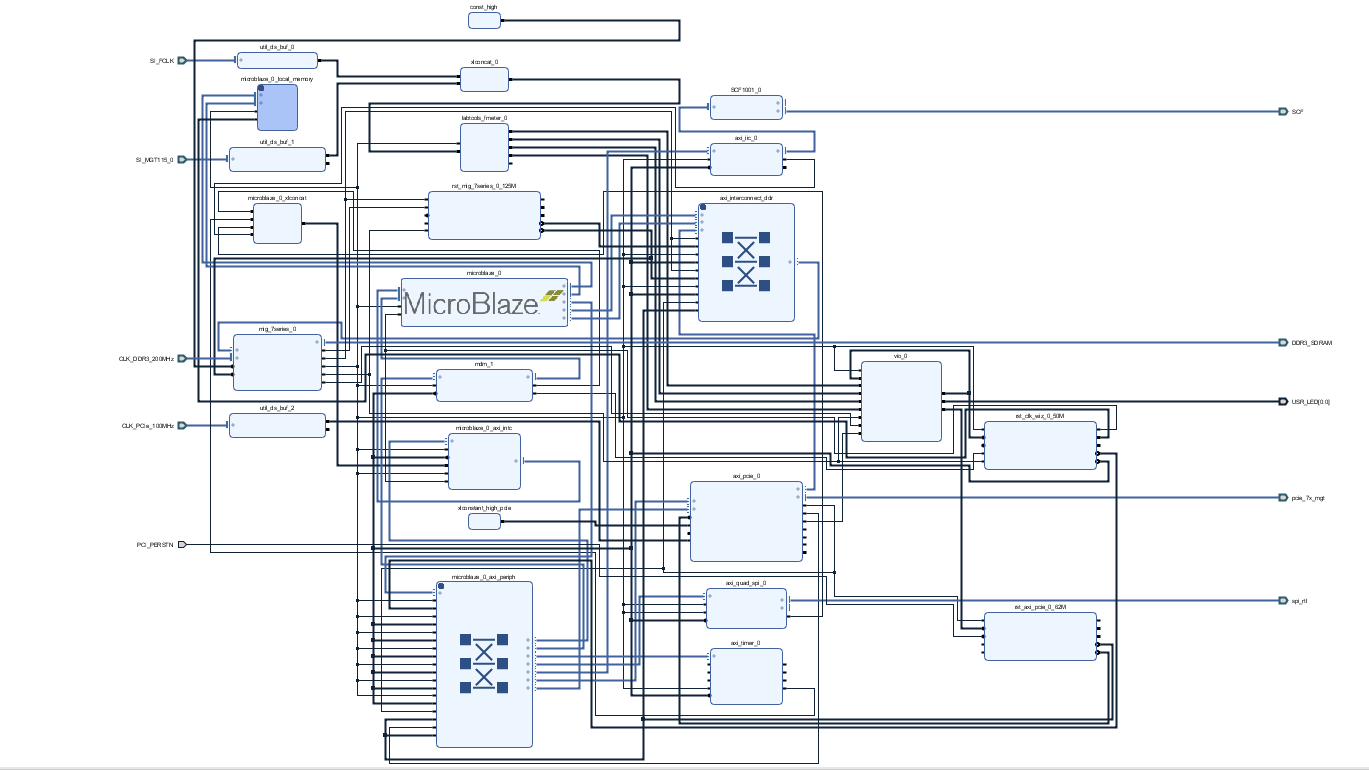
Block Design
...
Constrains
Basic module constrains
| Code Block | ||||
|---|---|---|---|---|
| ||||
set_property BITSTREAM.GENERAL.COMPRESS TRUE [current_design] set_property BITSTREAM.CONFIG_VOLTAGE 3.3.CONFIGRATE 66 [current_design] set_property CFGBVS VCCOCONFIG_VOLTAGE 1.8 [current_design] set_property BITSTREAM.CONFIG.USR_ACCESS TIMESTAMPCFGBVS GND [current_design] |
Design specific constrain
| Code Block | ||||
|---|---|---|---|---|
| ||||
set_property PACKAGECONFIG_PINMODE K2SPIx4 [get_ports {fclk[0]}]current_design] set_property IOSTANDARD LVCMOS18BITSTREAM.CONFIG.SPI_32BIT_ADDR YES [get_ports {fclk[0]}]current_design] set_property CLOCK_DEDICATED_ROUTE FALSE [get_nets fclk_IBUF[0]] |
Software Design - SDK/HSI
| HTML |
|---|
<!--
optional chapter
separate sections for different apps
--> |
For SDK project creation, follow instructions from:
Application
FSBL
Xilinx default FSBL
U-Boot
U-Boot.elf is generated with PetaLinux. SDK/HSI is used to generate Boot.bin.
Software Design - PetaLinux
| HTML |
|---|
<!--
optional chapter
Add "No changes." or "Activate: and add List"
--> |
For PetaLinux installation and project creation, follow instructions from:
Config
No changes.
U-Boot
No changes.
Device Tree
| Code Block | ||
|---|---|---|
| ||
/include/ "system-conf.dtsi"
/ {
};
|
Kernel
No changes.
Rootfs
No changes.
Applications
startup
Script App to load init.sh from SD Card if available.
See: \os\petalinux\project-spec\meta-user\recipes-apps\startup\files
Additional Software
| HTML |
|---|
<!--
Add Description for other Software, for example SI CLK Builder ...
--> |
No additional software is needed.
SDSoC Design
| HTML |
|---|
<!--
optional chapter for SDSoC only
-remove sections, if not supported
--> |
Description currently not available.
SDSoC Platform
SDSoC Demo Examples
SDSoC platform includes 21 demo projects demonstrating optimization techniques for Standalone and Linux targets with HW acceleration or in SW for fast compilation and debug. These projects have been downloaded and installed into the SDSoC platform from https://github.com/Xilinx/SDSoC_Examples
- array_partition
- burst_rw
- custom_data_type
- data_access_random
- dependence_inter
- direct_connect
- dma_sg
- dma_simple
- full_array_2d
- hello_vadd
- lmem_2rw
- loop_fusion
- loop_perfect
- loop_pipeline
- loop_reorder
- row_array_2d
- shift_register
- systolic_array
- sys_port
- wide_memory_rw
- window_array_2d
There are 3 larger Linux demo projects demonstrating video processing with data I/O from file to file. Source code of these projects have been installed into this platform from the Xilinx SDSoC 2016.4 release:
- file_io_manr_sobel
- file_io_optical
- file_io_sbm
These larger Linux demo projects demonstrate video processing with data I/O from file to file. Source code of these projects have been installed into this platform from demos present in the Xilinx SDSoC 2016.4 release.
Compilation steps in the SDSoC 2017.1 is identical to above described examples. File I/O demos support only the Linux target.
These three files use as an input larger video files. These files have to be present on the SD card as an input. Algorithms write output file to the SD card. These files can be visualized by YUV Player Deluxe and other players. To reduce size of the project, the video data files are not included.
Video input files can be found in the Xilinx SDSoC 2016.4 distribution:
- <xilinx install path>\SDx\2016.4\samples\file_io_manr_sobel\input.yuv
- <xilinx install path>\SDx\2016.4\samples\file_io_optical\route85_1920x1080.yuv
- <xilinx install path>\SDx\2016.4\samples\file_io_sbm\desk_1280x720.yuv
Array partition
This example shows how to use array partitioning to improve performance of a hardware function.
Key Concepts:
- Hardware Function Optimization
- Array Partitioning
Keywords:
- #pragma HLS ARRAY_PARTITION
- complete
Burst rw
This is a simple vector increment example which demonstrates usage of AXI4-master interface for burst read and write.
Key Concepts:
- Burst Access
Custom data type
This is a simple example of RGB to HSV conversion to demonstrate Custom Data Type usage in hardware accelerator. Xilinx HLS compiler supports custom data type to operate within the hardware function and also it acts as a memory interface between PL to DDR.
Key Concepts:
- Custom Data Type
Keywords:
- struct
- packed
- aligned
Data access random
This is a simple example of matrix multiplication (Row x Col) to demonstrate random data access pattern.
Key Concepts:
- Data Access Random
Keywords:
- #pragma HLS PIPELINE
- #pragma SDS access_pattern(a:RANDOM, b:RANDOM)
- #pragma SDS data copy
Dependence inter
This is a simple example to demonstrate inter dependence attribute using vertical convolution example. Using inter dependence attribute user can provide additional dependency details to compiler which allow compiler to perform unrolling/pipelining to get better performance.
Key Concepts:
- Inter Dependence
Keywords:
- DEPENDENCE
- inter
Direct connect
This is a simple example of matrix multiplication with matrix addition (Out = (A x B) + C) to demonstrate direct connection which helps to achieve increasing in system parallelism and concurrency.
Key Concepts:
- Direct Connection
- Multiple Accelerators
Keywords:
- #pragma SDS data access_pattern(in1:SEQUENTIAL, in2:SEQUENTIAL, out:SEQUENTIAL)
Dma sg
This example demonstrates how to use Scatter-Gather DMAs for data transfer to/from hardware accelerator.
Key Concepts:
- Scatter Gather DMA
Keywords:
- #pragma SDS access_parttern(a:SEQUENTIAL)
- #pragma SDS data_mover(a:AXIDMA_SG)
- #pragma SDS data copy
Dma simple
This example demonstrates how to insert Simple DMAs for data transfer between User program and hardware accelerator.
Key Concepts:
- Simple DMA
Keywords:
- #pragma SDS access_parttern(a:SEQUENTIAL)
- #pragma SDS data_mover(a:AXIDMA_SIMPLE)
- #pragma SDS data copy
Full array 2d
This is a simple example of accessing full data from 2D array.
Key Concepts:
- 2D data array access
Hello vadd
----------
This is a basic hello world kind of example which demonstrates how to achieve vector addition using hardware function.
Key Concepts:
- - Loop Pipelining
Keywords:
- - #pragma HLS PIPELINE
Lmem 2rw
This is a simple example of vector addition to demonstrate how to utilize both ports of Local Memory.
Key Concepts:
- Hardware Function Optimization
- 2port BRAM Utilization
- Two read/write Local Memory
Keywords:
- #pragma HLS UNROLL FACTOR=2
Loop fusion
This example will demonstrate how to fuse two loops into one to improve the performance of a C/C++ hardware function.
Key Concepts:
- Hardware Function Optimization
- Loop Fusion
- Loop Pipelining
Keywords:
- #pragma HLS PIPELINE
Loop perfect
This nearest neighbor example is to demonstrate how to achieve better performance using perfect loop.
Key Concepts:
- Loop perfect
Keywords:
- #pragma HLS PIPELINE
- #pragma HLS ARRAY_PARTITION
Loop pipeline
This example demonstrates how loop pipelining can be used to improve the performance of a hardware function.
Key Concepts:
- Loop Pipelining
Keywords:
- #pragma HLS PIPELINE
Loop reorder
This is a simple example of matrix multiplication (Row x Col) to demonstrate how to achieve better pipeline II factor by loop reordering.
Key Concepts:
- Hardware Function Optimization
- Loop Reorder to Improve II
Keywords:
- #pragma HLS PIPELINE
- #pragma HLS ARRAY_PARTITION
Row array 2d
This is a simple example of accessing each row of data from 2D array.
Key Concepts:
- Row of 2D data array access
Keywords:
- hls::stream
Shift register
This example demonstrates how to shift values in each clock cycle.
Key Concepts:
- Hardware Function Optimization
- Shift Register
- FIR
Keywords:
- #pragma HLS ARRAY_PARTITION
Systolic array
This is a simple example of matrix multiplication (Row x Col) to help developers learn systolic array based algorithm design. Note : Systolic array based algorithm design is well suited for FPGA.
Key Concepts:
- Systolic Array
Keywords:
- #pragma HLS PIPELINE
- #pragma HLS ARRAY_PARTITION
Sys port
This is a simple example which demonstrates sys_port usage.
Key Concepts:
- sys_port
- memory interface
- memory non-caching
Keywords:
- #pragma SDS data sys_port
- #pragms HLS PIPELINE
- sds_alloc_non_cacheable
Wide memory rw
This is a simple example of vector addition to demonstrate Wide Memory Access using structure data type of 128bit wide. Based on input argument type, sds++ compiler will figure out the memory interface datawidth of hardware accelerator.
Key Concepts:
- wide memory access
- burst read and write
- custom datatype
Keywords:
- struct
Window array 2d
This is a simple example of accessing window of data from 2D array.
Key Concepts:
- Window of 2D data array access
Keywords:
- #pragma HLS DATAFLOW
- #pragma HLS PIPELINE
- #pragma HLS stream
File IO Video Processing
Linux video processing application that reads input video from a file and writes out the output video to a file. Video processing includes Motion Adaptive Noise Reduction (MANR) followed by a Sobel filter for edge detection. You can run it by supplying a 1080p YUV422 file as input with limiting number of frames to a maximum of 20 frames.
Key Concepts:
- Video processing from file to file
- Direct connection of HW accelerated blocks
Select the "File IO Video Processing" template an compile for Linux target as project te22. Copy result to root of SD card. Copy also the input file input.yuv (82 944 000 bytes) to the root of the SD card. Login and cd to /media Run demo from terminal or from display+keyboard by comman ./te22.elf ./input.yuv 20 3 ./output.yuv
The output.yuv file contains 20 frames of 1080p vido in YUV422 format with computed edges. Copy output.yuv file to PC and visualise it in yuvplayer (size 1920x1080 colour YUV422).
File IO Dense Optical Flow
Linux video processing application that reads input video from a file and writes out the output video to a file. Video processing performs LK Dense Optical Flow over two Full HD frames video file. You can run it by supplying a 1080p YUV422 file route85_1920x1080.yuv as input.
Key Concept:s
- Video processing from file to file
- Direct connection of HW accelerated blocks
- Top down methodology with detailed description in Xilinx UG1235 (v2017.1) June 20. 2017.
Select the "File IO Dense Optical Flow" template an compile for Linux target as project te23. Copy result to root of SD card. Copy also the input file route85_1920x1080.yuv (8 294 400 bytes) to the root of the SD card. Login and cd to /media Run demo from terminal or from display+keyboard by command ./te23.elf
The OptFlow_1920x1080.yuv file is generated and stored on the SD card. It contains one 1080p frame in YUV422 format with computed dense optical flow vectors. Copy OptFlow_1920x1080.yuv file to PC and visualise it in yuvplayer (size 1920x1080 colour YUV422).
File IO Stereo Block Matching
Linux video processing application that reads input video from a file and writes out the output video to a file. Video processing performs Stereo Block Matching to calculate depth in a single sample stereo video file desk_1280x720.yuv in YUV422 format as input and single frame Disparity_640x720.yuv in YUV422 format as output, indicating the depth of objects.
Key Concepts:
- Video processing from file to file
- Bottom Up methodology with detailed description in Xilinx UG1235 (v2017.1) June 20. 2017.
Select the "File IO Stereo Block Matching" template an compile for Linux target as project te24. Copy result to root of SD card. Copy also the input file desk_1280x720.yuv (1 843 200 bytes) to the root of the SD card. Login and cd to /media Run demo from terminal or from display+keyboard by command ./te24.elf
...
BITSTREAM.CONFIG.SPI_BUSWIDTH 4 [current_design]
set_property BITSTREAM.CONFIG.M1PIN PULLNONE [current_design]
set_property BITSTREAM.CONFIG.M2PIN PULLNONE [current_design]
set_property BITSTREAM.CONFIG.M0PIN PULLNONE [current_design]

set_property BITSTREAM.CONFIG.USR_ACCESS TIMESTAMP [current_design] |
Design specific constrain
| Code Block | ||||
|---|---|---|---|---|
| ||||
#----------
#USER LED
# FEX11
set_property PACKAGE_PIN B21 [get_ports {USR_LED[0]}]
set_property IOSTANDARD LVCMOS18 [get_ports {USR_LED[0]}]
#----------
#CLK DDR3
set_property PACKAGE_PIN AC9 [get_ports CLK_DDR3_200MHz_clk_p]
set_property IOSTANDARD DIFF_SSTL15 [get_ports CLK_DDR3_200MHz_clk_p]
set_property IOSTANDARD DIFF_SSTL15 [get_ports CLK_DDR3_200MHz_clk_n]
#----------
#QSPI
set_property PACKAGE_PIN C23 [get_ports {spi_rtl_ss_io[0]}]
set_property IOSTANDARD LVCMOS18 [get_ports {spi_rtl_ss_io[0]}]
set_property PACKAGE_PIN B24 [get_ports spi_rtl_io0_io]
set_property PACKAGE_PIN A25 [get_ports spi_rtl_io1_io]
set_property PACKAGE_PIN B22 [get_ports spi_rtl_io2_io]
set_property PACKAGE_PIN A22 [get_ports spi_rtl_io3_io]
set_property IOSTANDARD LVCMOS18 [get_ports spi_rtl_io0_io]
set_property IOSTANDARD LVCMOS18 [get_ports spi_rtl_io1_io]
set_property IOSTANDARD LVCMOS18 [get_ports spi_rtl_io2_io]
set_property IOSTANDARD LVCMOS18 [get_ports spi_rtl_io3_io]
#----------
#IIC to CPLD
set_property PACKAGE_PIN G26 [get_ports SCF_cpld_1_scl]
set_property PACKAGE_PIN F25 [get_ports SCF_cpld_14_oe]
set_property PACKAGE_PIN G25 [get_ports SCF_cpld_16_sda]
set_property IOSTANDARD LVCMOS18 [get_ports SCF_cpld_1_scl]
set_property IOSTANDARD LVCMOS18 [get_ports SCF_cpld_14_oe]
set_property IOSTANDARD LVCMOS18 [get_ports SCF_cpld_16_sda]
#----------
#SI5338 CLKs
set_property PACKAGE_PIN H6 [get_ports {SI_MGT115_0_clk_p[0]}]

set_property PACKAGE_PIN G22 [get_ports {SI_FCLK_clk_p[1]}]
set_property PACKAGE_PIN D23 [get_ports {SI_FCLK_clk_p[2]}]
set_property PACKAGE_PIN G24 [get_ports {SI_FCLK_clk_p[0]}]
set_property IOSTANDARD LVDS_25 [get_ports {SI_FCLK_*}] |
| Code Block | ||||
|---|---|---|---|---|
| ||||
#----------
# FEX0
set_property PACKAGE_PIN B20 [get_ports {PCI_PERSTN}]
set_property IOSTANDARD LVCMOS18 [get_ports {PCI_PERSTN}]
#----------
set_property PACKAGE_PIN K6 [get_ports {CLK_PCIe_100MHz_clk_p[0]}]
set_property PACKAGE_PIN N4 [get_ports {pcie_7x_mgt_rxp[2]}]
set_property PACKAGE_PIN R4 [get_ports {pcie_7x_mgt_rxp[3]}]
set_property PACKAGE_PIN L4 [get_ports {pcie_7x_mgt_rxp[1]}]
set_property PACKAGE_PIN J4 [get_ports {pcie_7x_mgt_rxp[0]}] |
Software Design - SDK/HSI
| HTML |
|---|
<!--
optional chapter
separate sections for different apps
--> |
For SDK project creation, follow instructions from:
Application
SI5338 Initalisation
Si5338 I2C Configuration example.
Additional Software
| HTML |
|---|
<!--
Add Description for other Software, for example SI CLK Builder ...
--> |
SI5338 CLKBuilder
- Open Register Map File:"\test_board\misc\SI5338\RegisterMap.txt"
- Change CLK if needed
- Save project and generate "register_map.h"
- Overwrite "register_map.h" from SI5338 Init Application with generate file
Appx. A: Change History and Legal Notices
...
| HTML |
|---|
<!-- Generate new entry: 1:add new row below first 2:Copy Page Information Macro(date+user) Preview, Page Information Macro Preview 3.Update Metadate =Page Information Macro Preview+1 --> |
| Date | Document Revision | Authors | Description | |||||||||||||||||||||
|---|---|---|---|---|---|---|---|---|---|---|---|---|---|---|---|---|---|---|---|---|---|---|---|---|
|
|
|
| 2017 |
| .2 |
| 2017-11-28 |
| v.1 |
| Initial release | |||||||
| All |
|
Legal Notices
| Include Page | ||||
|---|---|---|---|---|
|
...
Overview
Content Tools