Page History
...
Linux with basic periphery of TE0808 TE0807 Starterkit (TEBF0808 Carrier).
...
| Date | Vivado | Project Built | Authors | Description | |||||
|---|---|---|---|---|---|---|---|---|---|
| 2018-01- | 1718 | 2017.4TE0808 | TE0807-StarterKit_noprebuilt-vivado_2017.4-build_05_ | 2018011709421320180118152938.zip | TE0808TE0807-StarterKit | _noprebuilt-vivado_2017.4-build_05_ | 2018011709423120180118152922.zip | John Hartfiel |
|
| 2018-01-15 | 2017.4 | TE0808-StarterKit-vivado_2017.4-build_03_20180115092306.zip | John Hartfiel |
| |||||
| 2017-12-18 | 2017.2 | TE0808-StarterKit_noprebuilt-vivado_2017.2-build_07_20171219151749.zip TE0808-StarterKit-vivado_2017.2-build_07_20171219151728.zip | John Hartfiel |
|
Release Notes and Know Issues
|
Release Notes and Know Issues
| HTML |
|---|
<!--
- add known Design issues and general Notes for the current revision
--> |
| Issues | Description | Workaround/Solution | To be fixed version |
|---|---|---|---|
| --- | --- | --- | --- |
Requirements
Software
| HTML |
|---|
<!-- -Add addneeded known Design issues and general Notes for the current revision --> |
...
Requirements
Software
| HTML |
|---|
<!-- Add needed external Software external Software --> |
| Software | Version | Note |
|---|---|---|
| Vivado | 2017.4 | needed |
| SDK | 2017.4 | needed |
| PetaLinux | 2017.4 | needed |
...
| Module Model | Board Part Short Name | PCB Revision Support | DDR | QSPI Flash | Others | Notes | |||||||||||||||||||||||||||||||||||||||||||||||||||||||
|---|---|---|---|---|---|---|---|---|---|---|---|---|---|---|---|---|---|---|---|---|---|---|---|---|---|---|---|---|---|---|---|---|---|---|---|---|---|---|---|---|---|---|---|---|---|---|---|---|---|---|---|---|---|---|---|---|---|---|---|---|---|
| TE0808-ES1 | es1 | REV02, REV03 | 2GB | 64MB | TE0808TE0807-01-ES2 | es2 | REV03, REV04REV01 | 2GB | 64MB | TE0808-2ES2 | 2es2 | REV03, REV04 | 2GB | 64MB | TE0808-04-09EG-1EA | 9eg_1ea | REV04 | 2GB | 64MB | TE0808-04-09EG-1EB | 9eg_1eb | REV04 | 4GB | 64MB | TE0808-04-09EG-1ED | 9eg_1eb | REV04 | 4GB | 64MB | 2,5 mm connector | TE0808-04-09EG-1EE | 9eg_1eb | REV04 | 4GB | 128MB | TE0808-04-09EG-1EL | 9eg_1eb | REV04 | 4GB | 128MB | 2,5 mm connector | TE0808-04-09EG-2IB | 9eg_2ib | REV04 | 4GB | 64MB | TE0808-04-09EG-2IE | 9eg_2ib | REV04 | 4GB | 128MB | TE0808-04-15EG-1EB | 15eg_1eb | REV04 | 4GB | 64MB | TE0808-04-15EG-1EE | 15eg_1eb | REV04 | 4GB | 128MB |
Note: Design contains also Board Part Files for TE0808 only configuration, this boart part files are not used for this reference design.
Design supports following carriers:
...
Additional HW Requirements:
...
Content
| HTML |
|---|
<!--
Remove unused content
--> |
For general structure and of the reference design, see Project Delivery
Design Sources
...
Note: Design contains also Board Part Files for TE0807 only configuration, this boart part files are not used for this reference design.
Design supports following carriers:
| Carrier Model | Notes |
|---|---|
| TEBF0808 | Used as reference carrier. |
Additional HW Requirements:
| Additional Hardware | Notes |
|---|
Content
| HTML |
|---|
<!--
Remove unused content
--> |
For general structure and of the reference design, see Project Delivery
Design Sources
| Type | Location | Notes |
|---|---|---|
| Vivado | <design name>/block_design <design name>/constraints <design name>/ip_lib | Vivado Project will be generated by TE Scripts |
| SDK/HSI | <design name>/sw_lib | Additional Software Template for SDK/HSI and apps_list.csv with settings for HSI |
| PetaLinux | <design name>/os/petalinux | PetaLinux template with current configuration |
Additional Sources
| Type | Location | Notes |
|---|---|---|
| SI5345 | <design name>/misc/Si5345 | SI5345 Project with current PLL Configuration |
Prebuilt
| HTML |
|---|
<!--

<table |
Additional Sources
...
Prebuilt
| HTML |
|---|
<!--

<table width="100%">
<tr> <th>File                                 </th> <th>File-Extension</th>  <th>Description                                                                              </th> </tr>
<tr> <td>BIF-File                             </td> <td>*.bif         </td>  <td>File with description to generate Bin-File                                               </td> </tr>
<tr> <td>BIN-File                             </td> <td>*.bin         </td>  <td>Flash Configuration File with Boot-Image (Zynq-FPGAs)                                    </td> </tr>
<tr> <td>BIT-File                             </td> <td>*.bit         </td>  <td>FPGA Configuration File                                                                  </td> </tr>
<tr> <td>DebugProbes-File                     </td> <td>*.ltx         </td>  <td>Definition File for Vivado/Vivado Labtools Debugging Interface                           </td> </tr>
<tr> <td>Debian SD-Image                      </td> <td>*.img         </td>  <td>Debian Image for SD-Card                                                                </td> </tr>
<tr> <td>Diverse Reports                      </td> <td>  ---         </td>  <td>Report files in different formats                                                        </td> </tr>
<tr> <td>Hardware-Platform-Specification-Files</td> <td>*.hdf         </td>  <td>Exported Vivado Hardware Specification for SDK/HSI                                       </td> </tr>
<tr> <td>LabTools Project-File                </td> <td>*.lpr         </td>  <td>Vivado Labtools Project File                                                             </td> </tr>
<tr> <td>MCS-File                             </td> <td>*.mcs         </td>  <td>Flash Configuration File with Boot-Image (MicroBlaze or FPGA part only)                  </td> </tr>
<tr> <td>MMI-File                             </td> <td>*.mmi         </td>  <td>File with BRAM-Location to generate MCS or BIT-File with *.elf content (MicroBlaze only) </td> </tr>
<tr> <td>OS-Image                             </td> <td>*.ub          </td>  <td>Image with Linux Kernel (On Petalinux optional with Devicetree and RAM-Disk)             </td> </tr>
<tr> <td>Software-Application-File            </td> <td>*.elf         </td>  <td>Software Application for Zynq or MicroBlaze Processor Systems                            </td> </tr>
<tr> <td>SREC-File                            </td> <td>*.srec        </td>  <td>Converted Software Application for MicroBlaze Processor Systems                          </td> </tr>
</table>
-->
|
...
Reference Design is available on:
Design Flow
| HTML |
|---|
<!-- Basic Design Steps Add/ Remove project specific --> |
...
- _create_win_setup.cmd/_create_linux_setup.sh and follow instructions on shell:
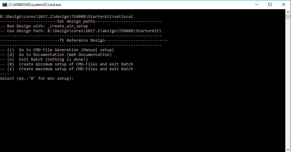
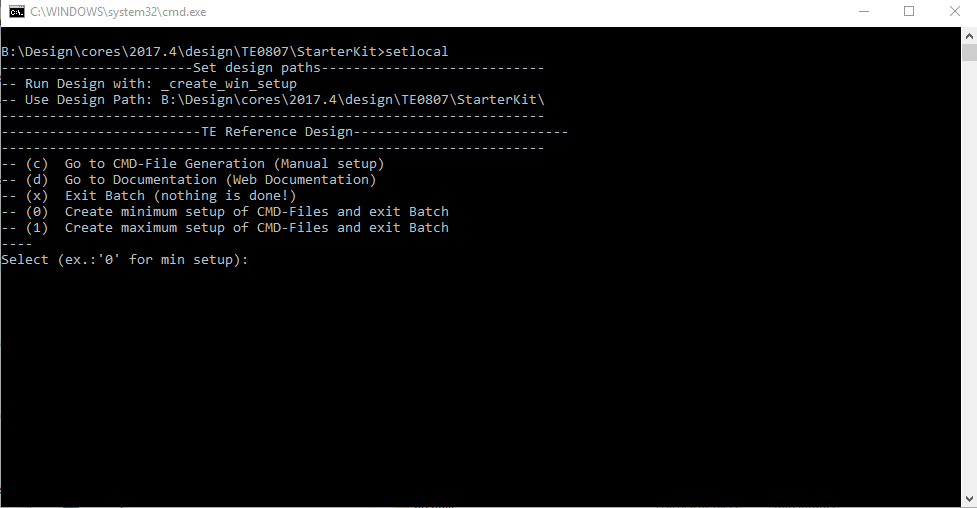
- Press 0 and enter for minimum setup
- (optional Win OS) Generate Virtual Drive or use short directory for the reference design (for example x:\<design name>)
- Create Project
- Select correct device and Xilinx install path on "design_basic_settings.cmd" and create Vivado project with "vivado_create_project_guimode.cmd"
Note: Select correct one, see TE Board Part Files
Important: Use Board Part Files, which ends with *_tebf0808
- Select correct device and Xilinx install path on "design_basic_settings.cmd" and create Vivado project with "vivado_create_project_guimode.cmd"
- Create HDF and export to prebuilt folder
- Run on Vivado TCL: TE::hw_build_design -export_prebuilt
Note: Script generate design and export files into \prebuilt\hardware\<short dir>. Use GUI is the same, except file export to prebuilt folder
- Run on Vivado TCL: TE::hw_build_design -export_prebuilt
- Create Linux (bl31.elf, uboot.elf and image.ub) with exported HDF
- HDF is exported to "prebuilt\hardware\<short name>"
Note: HW Export from Vivado GUI create another path as default workspace. - Create Linux images on VM, see PetaLinux KICKstart
- Use TE Template from /os/petalinux
Note: run init_config.sh before you start petalinux config. This will set correct temporary path variable.
- Use TE Template from /os/petalinux
- HDF is exported to "prebuilt\hardware\<short name>"
- Add Linux files (bl31.elf, uboot.elf and image.ub) to prebuilt folder
- "prebuilt\os\petalinux\default" or "prebuilt\os\petalinux\<short name>"
Notes: Scripts select "prebuilt\os\petalinux\<short name>", if exist, otherwise "prebuilt\os\petalinux\default"
- "prebuilt\os\petalinux\default" or "prebuilt\os\petalinux\<short name>"
- Generate Programming Files with HSI/SDK
- Run on Vivado TCL: TE::sw_run_hsi
Note: Scripts generate applications and bootable files, which are defined in "sw_lib\apps_list.csv" - (alternative) Start SDK with Vivado GUI or start with TE Scripts on Vivado TCL: TE::sw_run_sdk
Note: See SDK Projects
- Run on Vivado TCL: TE::sw_run_hsi
...
- Prepare HW like described on section 46042644 Programming
- Connect UART USB (JTAG XMOD)
- Select SD Card as Boot Mode (or QSPI - depending on step 1)
Note: See TRM of the Carrier, which is used. - (Optional) Insert PCIe Card (detection depends on Linux driver. Only some basic drivers are installed)
- (Optional) Connect Sata Disc
- (Optional) Connect DisplayPort Monitor (List of usable Monitors: https://www.xilinx.com/support/answers/68671.html)
- (Optional) Connect Network Cable
- Power On PCB
Note: 1. ZynqMP Boot ROM loads PMU Firmware and FSBL from SD into OCM, 2. FSBL loads ATF(bl31.elf) and U-boot from SD/QSPI into DDR, 3. U-boot load Linux from SD into DDR.
...
| HTML |
|---|
<!--
Description of Block Design, Constrains...
BD Pictures from Export...
--> |
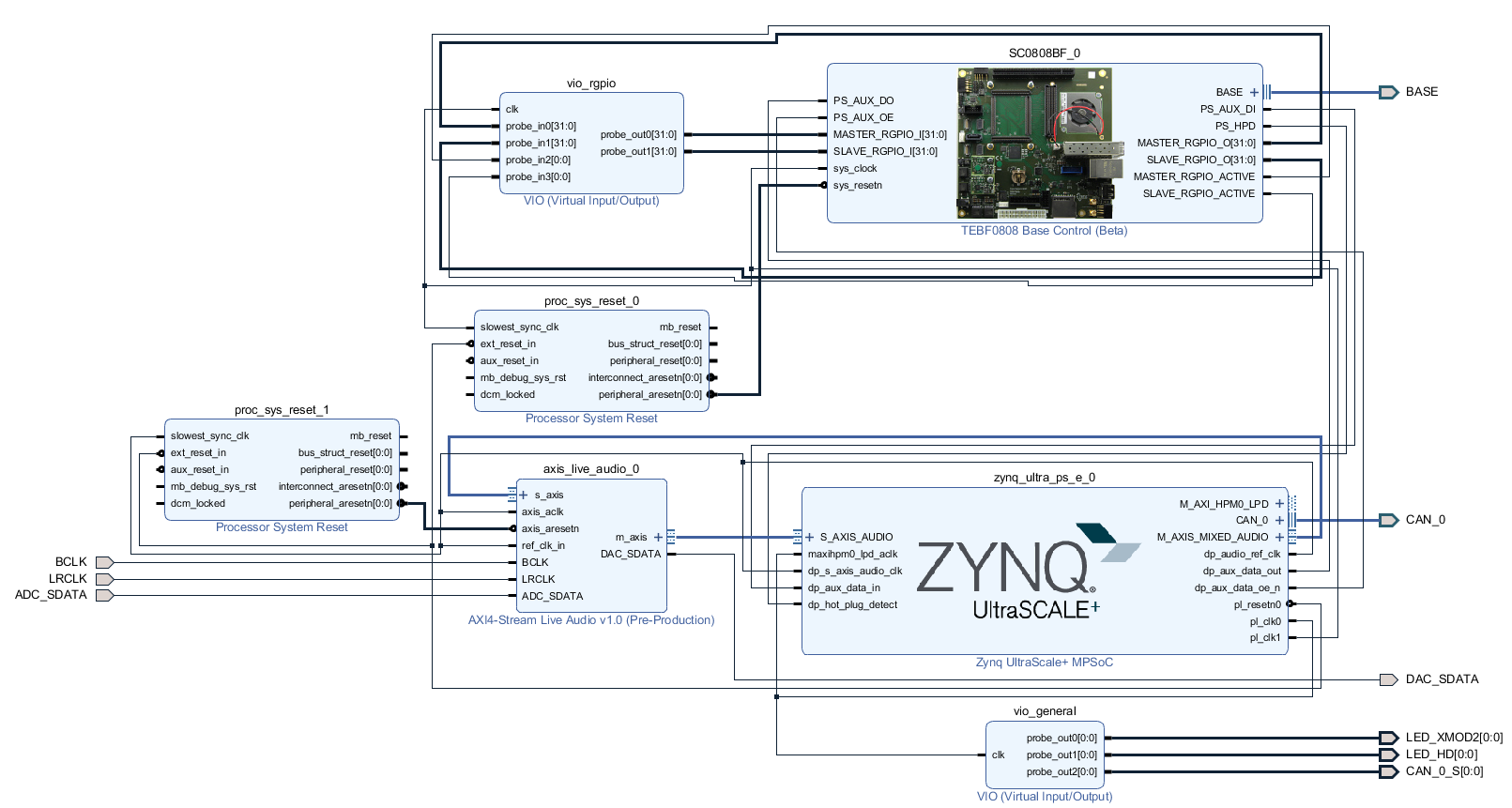
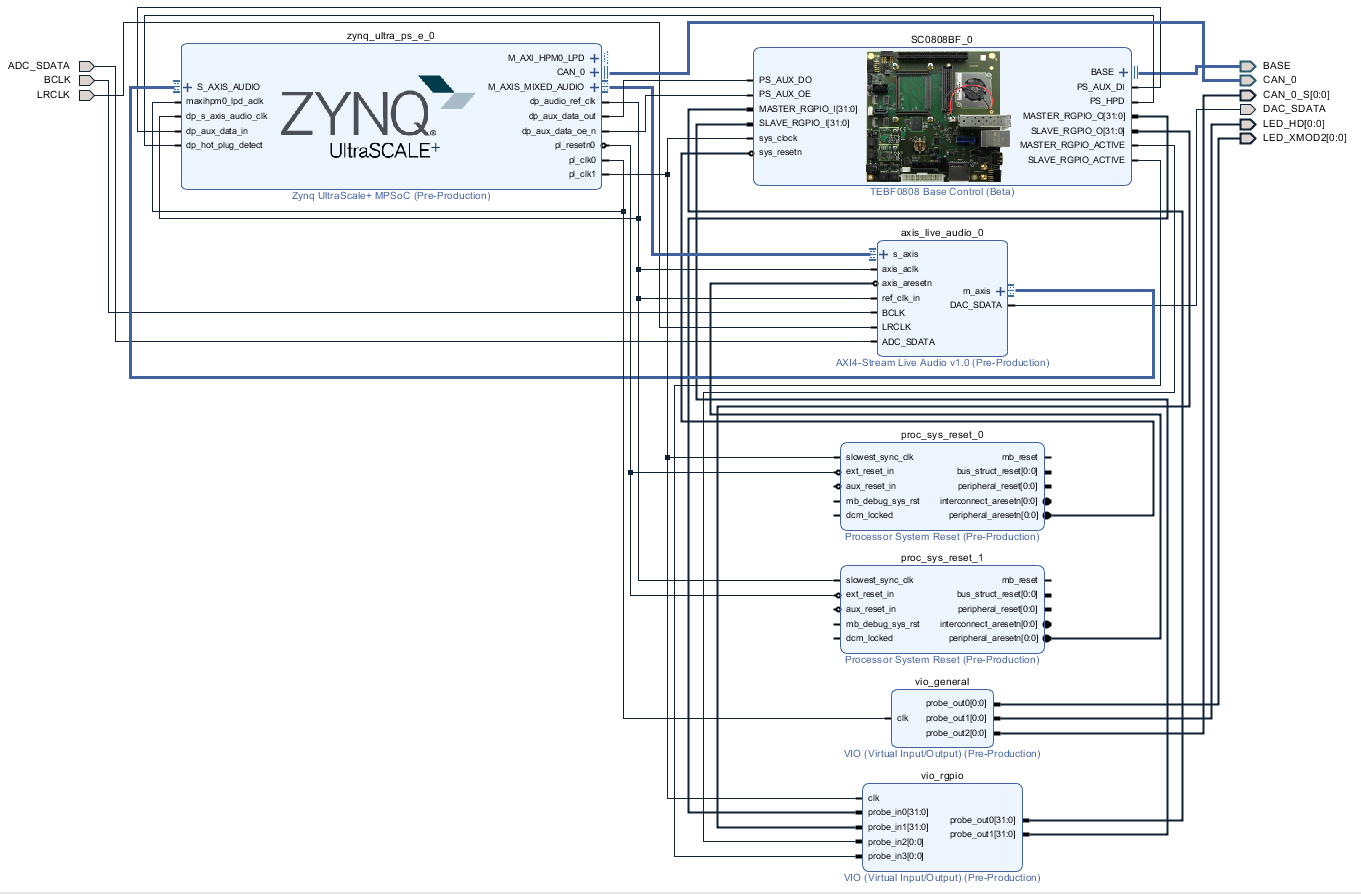
Block Design
PS Interfaces
Activated interfaces:
...
> |
Block Design
PS Interfaces
Activated interfaces:
| Type | Note |
|---|---|
| DDR | |
| QSPI | MIO |
| SD0 | MIO |
| SD1 | MIO |
| CAN0 | EMIO |
| I2C0 | MIO |
| PJTAG0 | MIO |
| UART0 | MIO |
| GPIO0 | MIO |
| SWDT0..1 | |
| TTC0..3 | |
| GEM3 | MIO |
| USB0 | MIO/GTP |
| PCIe | MIO/GTP |
| SATA | GTP |
Constrains
Basic module constrains
| Code Block | ||||
|---|---|---|---|---|
| ||||
set_property BITSTREAM.GENERAL.COMPRESS TRUE [current_design]
set_property BITSTREAM.CONFIG.UNUSEDPIN PULLNONE [current_design] |
Design specific constrain
| Code Block | ||||
|---|---|---|---|---|
| ||||
#LED_HD SC0 J3:31 |
Constrains
Basic module constrains
| Code Block | ||||
|---|---|---|---|---|
| ||||
set_property BITSTREAM.GENERAL.COMPRESS TRUE [current_design]
set_property BITSTREAM.CONFIG.UNUSEDPIN PULLNONE [current_design] |
Design specific constrain
| Code Block | ||||
|---|---|---|---|---|
| ||||
#LED_HD SC0 J3:31 set_property PACKAGE_PIN J14 [get_ports {LED_HD[0]}] set_property IOSTANDARD LVCMOS18 [get_ports {LED_HD[0]}] #LED_XMOD SC17 J3:48 set_property PACKAGE_PIN B13 [get_ports {LED_XMOD2[0]}] set_property IOSTANDARD LVCMOS18 [get_ports {LED_XMOD2[0]}] #System Controller IP set_property PACKAGE_PIN A15 [get_ports BASE_sc10_io] set_property PACKAGE_PIN B15 [get_ports BASE_sc11] set_property PACKAGE_PIN C13 [get_ports BASE_sc12] set_property PACKAGE_PIN C14K11 [get_ports BASE_sc13{LED_HD[0]}] set_property PACKAGE_PINIOSTANDARD E13LVCMOS18 [get_ports BASE_sc14] {LED_HD[0]}] #LED_XMOD SC17 J3:48 set_property PACKAGE_PIN E14B12 [get_ports BASE_sc15{LED_XMOD2[0]}] set_property PACKAGE_PINIOSTANDARD G13LVCMOS18 [get_ports BASE_sc5]{LED_XMOD2[0]}] #System Controller IP #J3:32 set_property PACKAGE_PIN J15J12 [get_ports BASE_sc10_sc6io] #J3:34 set_property PACKAGE_PIN K15K13 [get_ports BASE_sc7sc11] #J3:36 set_property IOSTANDARDPACKAGE_PIN LVCMOS18A13 [get_ports BASE_sc5sc12] #J3:38 set_property IOSTANDARDPACKAGE_PIN LVCMOS18A14 [get_ports BASE_sc6sc13] #J3:40 set_property IOSTANDARDPACKAGE_PIN LVCMOS18E12 [get_ports BASE_sc7sc14] #J3:42 set_property IOSTANDARDPACKAGE_PIN LVCMOS18F12 [get_ports BASE_sc10_iosc15] #J3:41 set_property IOSTANDARDPACKAGE_PIN LVCMOS18E14 [get_ports BASE_sc11sc5] #J3:45 set_property IOSTANDARDPACKAGE_PIN LVCMOS18C12 [get_ports BASE_sc12sc6] #J3:47 set_property IOSTANDARDPACKAGE_PIN LVCMOS18D12 [get_ports BASE_sc13sc7] set_property IOSTANDARD LVCMOS18 [get_ports BASE_sc14sc5] set_property IOSTANDARD LVCMOS18 [get_ports BASE_sc15sc6] # PLL #setset_property PACKAGE_PINIOSTANDARD AH6LVCMOS18 [get_ports {si570_clk_p[0]}BASE_sc7] #setset_property IOSTANDARD LVDSLVCMOS18 [get_ports {si570BASE_clk_p[0]}sc10_io] #setset_property IOSTANDARD LVDSLVCMOS18 [get_ports {si570_clk_n[0]}] # Clocks #setBASE_sc11] set_property PACKAGE_PINIOSTANDARD J8LVCMOS18 [get_ports {B229_CLK1_clk_p[0]}] #setBASE_sc12] set_property PACKAGE_PINIOSTANDARD F25LVCMOS18 [get_ports {B128_CLK0_clk_p[0]}] # SFP #setBASE_sc13] set_property PACKAGE_PINIOSTANDARD G8LVCMOS18 [get_ports {B230_CLK0_clk_p}] # B230_RX3_P #setBASE_sc14] set_property PACKAGE_PINIOSTANDARD A4LVCMOS18 [get_ports {SFP1BASE_rxp}sc15] # B230_TX3_PPLL #J4:74 #set_property PACKAGE_PIN A8AF15 [get_ports {SFP1_txp}] # B230_RX2_Psi570_clk_p[0]}] #set_property PACKAGE_PINIOSTANDARD B2LVDS [get_ports {SFP2_rxp}] # B230_TX2_Psi570_clk_p[0]}] #set_property PACKAGE_PINIOSTANDARD B6LVDS [get_ports {SFP2_txpsi570_clk_n[0]}] # Audio Codec #LRCLK J3:49 B47_L9_N #BCLK set_property PACKAGE_PIN G14 [get_ports LRCLK ] #BCLK J3:51 B47_L9_P #DAC_SDATA J3:53 B47_L7_N #ADC_SDATA J3:55 B47_L7_P set_property PACKAGE_PIN G14 [get_ports LRCLK ] set_property PACKAGE_PIN G15H14 [get_ports BCLK ] #DAC_SDATA J3:53 B47_L7_N set_property PACKAGE_PIN E15C13 [get_ports DAC_SDATA ] #ADC_SDATA J3:55 B47_L7_P set_property PACKAGE_PIN F15D14 [get_ports ADC_SDATA ] set_property IOSTANDARD LVCMOS18 [get_ports LRCLK ] set_property IOSTANDARD LVCMOS18 [get_ports BCLK ] set_property IOSTANDARD LVCMOS18 [get_ports DAC_SDATA ] set_property IOSTANDARD LVCMOS18 [get_ports ADC_SDATA ] # CAN #CAN RX SC19 J3:52 B47_L2L10_P #CAN TX SC18 J3:50 B47_L2L10_N #CAN S SC16 J3:46 B47_L3L12_N set_property PACKAGE_PIN A13A12 [get_ports CAN_0_S ] set_property IOSTANDARD LVCMOS18 [get_ports CAN_0_S ] set_property PACKAGE_PIN B14C14 [get_ports CAN_0_rx ] set_property IOSTANDARD LVCMOS18 [get_ports CAN_0_rx ] set_property PACKAGE_PIN A14B14 [get_ports CAN_0_tx ] set_property IOSTANDARD LVCMOS18 [get_ports CAN_0_tx ] |
...
Xilinx default PMU firmware.
Hello
...
TE0807
Hello TE0808 TE0807 is a Xilinx Hello World example as endless loop instead of one console output.
...
- Install and start ClockBuilder
- Open "/misc/SI5345/Si5345-RevB-08080807-02A-Project.slabtimeproj"
- Modify settings
- Export → Register File → select C code header → save to file
- Replace Header files from FSBL template with generated file
...
| Date | Document Revision | Authors | Description | ||||||||||||||||||||||||||||||||
|---|---|---|---|---|---|---|---|---|---|---|---|---|---|---|---|---|---|---|---|---|---|---|---|---|---|---|---|---|---|---|---|---|---|---|---|
|
|
|
| 2018-01-15 | v.4 | John Hartfiel
| 2017-12-20 | v.2 | John Hartfiel | Release 2017.2||||||||||||||||||||||||||
| All |
|
...
Overview
Content Tools