Page History
...
The Trenz Electronic TEB0724-01 is a developement carrier board for the TE0724 and compatible modules. It facilitates easy access to all on the module available features.
| HTML |
|---|
<!-- Use short link the Wiki Ressource page: for example: http://trenz.org/te0720-info List of available short links: https://wiki.trenz-electronic.de/display/CON/Redirects --> |
...
- Samtec 160 pin board to board connector for 4,0 cm x 6,0 cm module
- 10x 2x6 Pin Pmods, (8 usable as dual Pmods, 1x single Pmod, 1x I2C compatible Pmod)
- MicroUSB to JTAG/UART bridge
- CAN screw terminal
- RJ45 Gigabit Ethernet MagJack connector
- 6x LED, 2x Push Buttons on FPGA
- 1 LED and 1 Push Button on PS
- Power and Reset Push Buttons
- On-board Power Protection Circuit and Power on LED
...
| Scroll Title | ||||||||||||||||||||||||||||||
|---|---|---|---|---|---|---|---|---|---|---|---|---|---|---|---|---|---|---|---|---|---|---|---|---|---|---|---|---|---|---|
| ||||||||||||||||||||||||||||||
|

Main Components
| Scroll Title | ||||
|---|---|---|---|---|
| ||||
|
Table 1: TE0724-01 main components.
Initial Delivery State
Not programmed.
...
Storage device name
...
Content
...
Notes
...
..
...
..
...
|
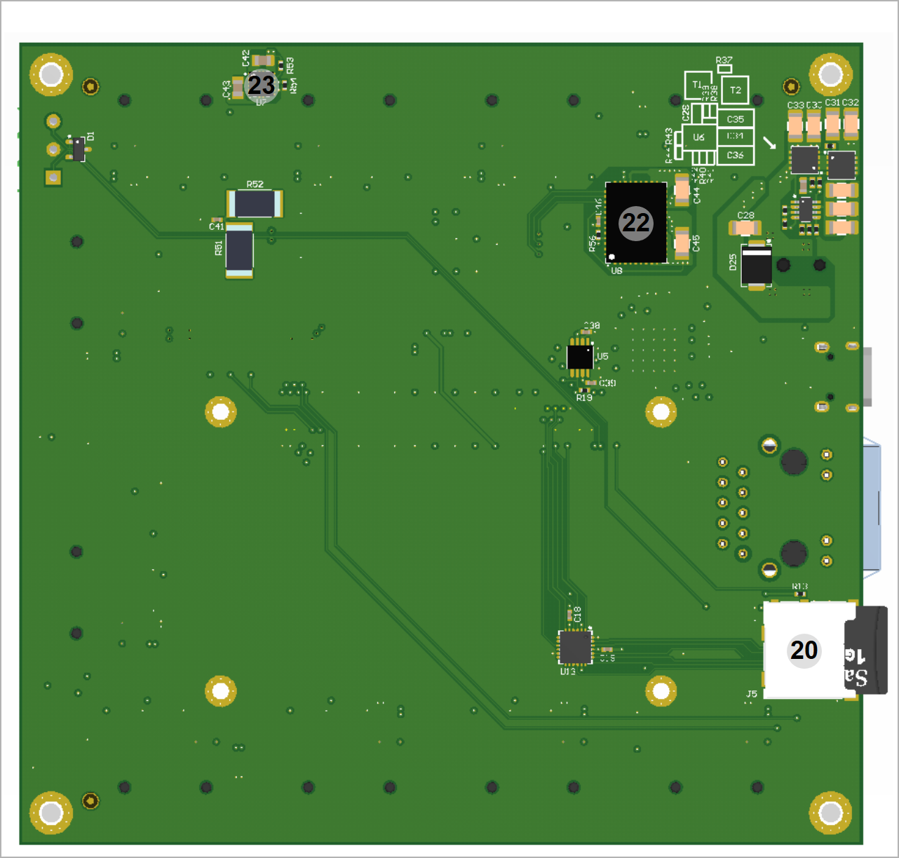
Table 1: TE0724-01 main components.
- Module connector for 4,0x6.0 cm module
- Pmods usabel as dual Pmods, J10, J11, J12, J13, J14, J15, J16, J17
- Pmod (single), J20
- I2C Pmod, J21
- CAN screw terminal, J2
- 5V 2.1mm input jack, J18
- microUSB J4
- USB to JTAG/UART bridge FT2232H, U1
- Configuration EEPROM U3
- RJ45 Gigabit Ehternet Jack, J3
- Power Button, S1
- Resetreq Button, S3
- User Button PS, S5
- User LED (green) PS, D8
- 2x User Button PL, S2, S4
- 6x User LEDs (red) PL, D2-D7
- Power LED (green), D36
- microSD Card Slot, J5
Initial Delivery State
Not programmed.
Storage device name | Content | Notes |
|---|---|---|
| FTDI Configuration EEPROM U3 | Empty | Not programmed. |
Table 1: Initial delivery state of programmable devices on the moduleboard.
Boot Process
By default the ... supports QSPI and SD Card boot modes which is controlled by the MODE input signal from the B2B connector JM..
...
MODE Signal State
...
For selection of the bootdevice the Pins
High or open | SD Card |
Low or ground | QSPI Interface |
...
Overview
Content Tools