Page History
...
| Page properties | ||||
|---|---|---|---|---|
| ||||
In this section you must explain how to power on the board and run the Reference Design (test board) on the particular module. The main points must be mentioned are:
|
| Scroll pdf ignore | |
|---|---|
Table of Contents
|
...
| Scroll Title | |||||||||||||||||||||||||||||||||||||||||||||||
|---|---|---|---|---|---|---|---|---|---|---|---|---|---|---|---|---|---|---|---|---|---|---|---|---|---|---|---|---|---|---|---|---|---|---|---|---|---|---|---|---|---|---|---|---|---|---|---|
| |||||||||||||||||||||||||||||||||||||||||||||||
|
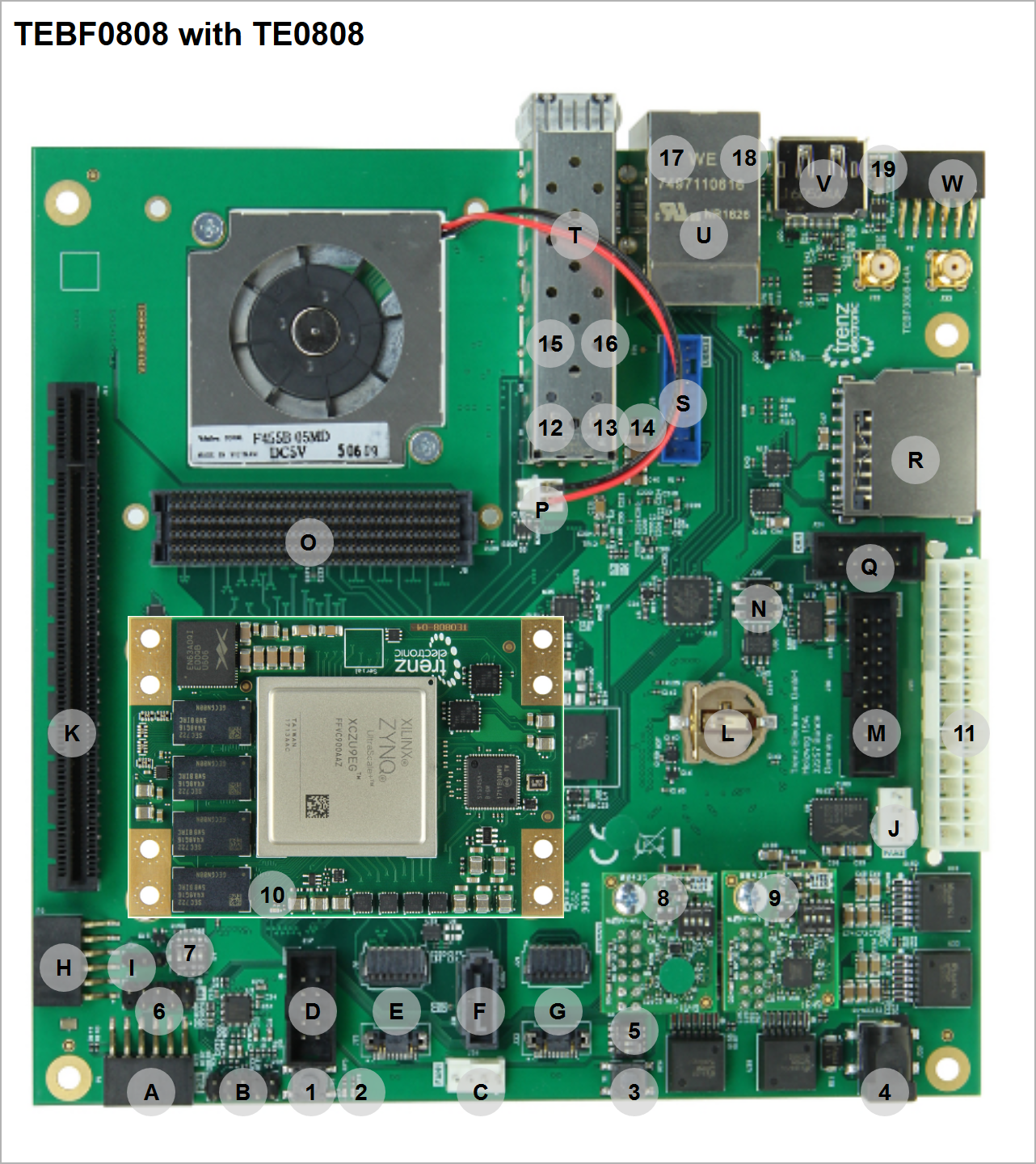
- Reset Button S2
- LEDs D7 Red (Usage: status) and D6 Green (Usage: status)
- Reset Button S1
- Power Jack 2.1mm (optional 12V power input)
- S5 DIP for Boot Mode and FMCVADJ
- Enclosure Pin header(Reset and Power Button, HD LED (Usage: status/user) and Power LED (Usage: status/user))
- S4 DIP for CPLD access and power control
- XMOD J12 with green dot for Module JTAG and UART, XMOD LED D4 Red used for status information
- XMOD J28 for CPLD,FMC JTAG and Firmware ID over UART(need CPLD Firmware 7 or newer) , XMOD LED D4 Red used for status information
- FPGA Done LED (location varies slightly depending on module)
- ATX Power Connector (Main 12V and 5V Power supply), recommended power supply connector
- SFP LED D1 Red
- SFP LED D8 Green
- SFP LED D9 Red
- SFP LED D10 Green
- ETH LED Yellow
- ETH LED Green/Orange
- LEDs D4 Green (Usage: status/user) and D5 Red (Usage: status/user)
Power supply
| Page properties | ||||
|---|---|---|---|---|
| ||||
The input power supply must be mentioned. Add Link to overview picture with connector label. |
...
Overview
Content Tools