Page History
This demo provides an example on how to use the communication interface provided in the modules firmware,
to setup the pre-amplification and trigger an ADC measurement.
The module saves after a trigger event 1 million samples of ADC measurement in its SDRAM.
Those values are gathered in parts of 16 kbytes and converted from RAW ADC data to standard integers and
floating point numbers.
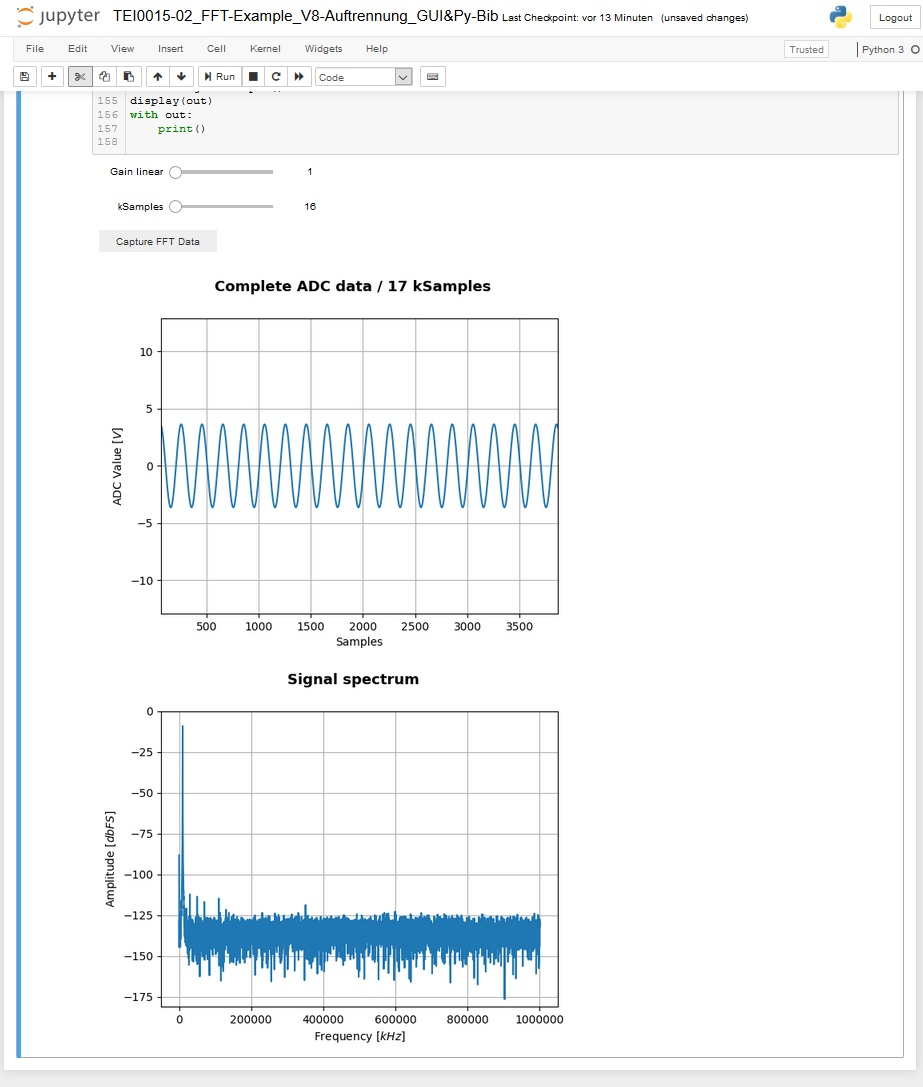
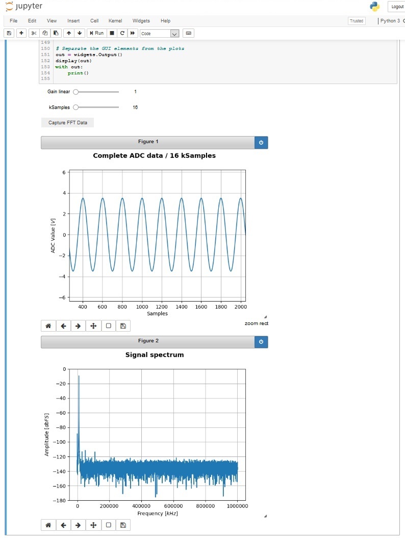
The signal is plotted, showing its value over time, and Fourier transformed, showing its frequency works with the modules TEI0015 and TEI0016. In this example the ADC of the module measures one million samples
and stores them inside its SD-RAM. The data is collected, converted and shown as graph plot, showing its value and
time behaviour and for the second graph a Fourier transformation is performed, showing the Frequency spectrum.
The user can adjust easily access the pre-amplification and the length of the data to be processed.In this demo the general approach on how to communicate with the module and perform high speed measurements with
the ADC are shownprocessed and plotted part of the data
through a GUI.
Communicating with module:
To communicate with the module, a serial comport port with a speed set to 115200 bits needs to be opened.
Commands consists of a single single character in UTF-8 encoding.
It is good practice to communication with the module following these steps:
...
These steps apply also for read operations.
Using the ADC for high speed consecutive measurements
The module provides a method to gather highly accurate consecutive ADC measurements in a single event.
In this mode of operation, one mega sample of ADC values are performed and stored inside the modules
SD-RAM.
...
- Open a serial comport
- Send the command "1", "2", "4" or "8" for the ADC pre-amplification
- Send the command "t" to trigger the consecutive measurement.
(The module always measures 1 MSample of data into its SD-RAM) - Clear the PCs serial comport input buffer of the opened comport
- Send the command "+" or "*", to the module, it then transmits 128 or 16384 Samples of ADC values
- Read the amount of ADC values in one chunk of 128 or 16384 samples from the PCs serial input buffer of the PC
(Otherwise there is a high possibility of a misalignment of nibbles) - Repeat the reading of chunks to a maximum of 1 mega sample
- Close the comport
...
Information to convert the RAW ADC data into standard integer values.
Module TEI0015 - AD4003BCPZ-RL7
Resolution: 18-bit / 5 nibbles
Maximum sampling rate: 2 MSPS
Order of Values:
| Hex | Dec | Hex | Dec | ||
|---|---|---|---|---|---|
| Mid scale | 0x00000 | 0 | |||
| Positive 1 LSB | 0x00001 | 1 | to full scale -1 LSB | 0x1ffff | 131071 |
| Negative full scale | 0x20000 | 131072 | to -1 LSB | 0x3FFFF | 262143 |
The layout of the ADC circuit is further described in the Analog Devices circuit note CN-0385.
Module TEI0016 -
...
ADAQ7988 / ADAQ7980
Resolution: 16-bit / 4 nibbles
Maximum sampling rate: 0.5 MSPSMSps / 1 MSps
Order of Values:
| Hex | Dec | Hex | Dec | ||
|---|---|---|---|---|---|
| Negative full scale is | 0x0000 | 0 | to -1 LSB | 0x7fff | 32767 |
| Mid scale is | 0x8000 | 32768 | |||
| Positive 1 LSB | 0x8001 | 32769 | to full scale | 0xffff | 65536 |
The layout of the ADC circuit is further described in the Analog Devices circuit note CN-0393.
...
Overview
Content Tools