...
| Scroll Title |
|---|
| anchor | Figure_OV_BD |
|---|
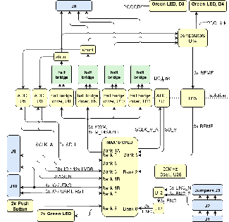
| title | CR00140 block diagram |
|---|
|
| Scroll Ignore |
|---|
| draw.io Diagram |
|---|
| border | true |
|---|
| viewerToolbar | true |
|---|
| |
|---|
| fitWindow | false |
|---|
| diagramName | BD_CR00140 |
|---|
| simpleViewer | false |
|---|
| width | |
|---|
| diagramWidth | 650 |
|---|
| revision | 1114 |
|---|
|
|
| Scroll Only |
|---|
|
|
Main Components
...
| Scroll Title |
|---|
| anchor | Table_SIP_JTG |
|---|
| title | JTAG pins connection |
|---|
|
| Scroll Table Layout |
|---|
| orientation | portrait |
|---|
| sortDirection | ASC |
|---|
| repeatTableHeaders | default |
|---|
| style | |
|---|
| widths | |
|---|
| sortByColumn | 1 |
|---|
| sortEnabled | false |
|---|
| cellHighlighting | true |
|---|
|
JTAG Signal | B2B Connector | Pin header | Notes |
|---|
| TMS | J9-55 | J10-5 | pull up | | TDI | J9-51 | J10-9 | pull up | | TDO | J9-53 | J10-3 |
| | TCK | J9-59 | J10-1 | pull down | | JTAG_EN | J9-57 | - | pull up |
|
On-board Peripherals
| Page properties |
|---|
|
Notes : - add subsection for every component which is important for design, for example:
- Two 100 Mbit Ethernet Transciever PHY
- USB PHY
- Programmable Clock Generator
- Oscillators
- eMMCs
- RTC
- FTDI
- ...
- DIP-Switches
- Buttons
- LEDs
|
Sensor Interface
The pin headers J1, J2 and J3 constitute the sensor interface. It can be e.g. used with Encoders or Hall sensores. J3 is the selector between differential sensor interface (J2) or single ended sensors (J1). Connecting sensors is only allowed to one of the two pinheaders, the other one has to stay unconnected. In the figure below the jumper configuration of J3 to enable one or the other type of sensor interface is depicted.
| Scroll Title |
|---|
| anchor | Figure_OV_Jumpers |
|---|
| title | CR00140 Jumpers |
|---|
|
| Scroll Ignore |
|---|
| draw.io Diagram |
|---|
| border | true |
|---|
| viewerToolbar | true |
|---|
| |
|---|
| fitWindow | false |
|---|
| diagramName | CR00140_Jumper |
|---|
| simpleViewer | false |
|---|
| width | |
|---|
| diagramWidth | 242 |
|---|
| revision | 6 |
|---|
|
|
| Scroll Only |
|---|
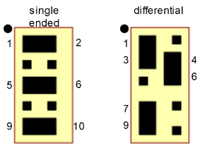 Image Added Image Added
|
|
The pinheaders are for connection of the sensors are further described in the following table. For differential configuration 100 Ohm parallel termination is used.
| Scroll Title |
|---|
| anchor | Table_SIP_Sensors |
|---|
| title | Sensor pins connection |
|---|
|
| Scroll Table Layout |
|---|
| orientation | portrait |
|---|
| sortDirection | ASC |
|---|
| repeatTableHeaders | default |
|---|
| style | |
|---|
| widths | |
|---|
| sortByColumn | 1 |
|---|
| sortEnabled | false |
|---|
| cellHighlighting | true |
|---|
|
Signal | Pin J1 (singel ended) | Pin J2 (differential) |
|---|
| ISO_ENC_A_P | 3 | 6 | | ISO_ENC_A_N | - | 5 | | ISO_ENC_B_P | 5 | 8 | | ISO_ENC_B_N | - | 7 | | ISO_ENC_I_P | 2 | 10 | | ISO_ENC_I_N | - | 9 | | DGND | 4 | 3 | | +5.0V_D | 1, 6 | 2 |
|
On-board Peripherals
| Page properties |
|---|
|
Notes : - add subsection for every component which is important for design, for example:
- Two 100 Mbit Ethernet Transciever PHY
- USB PHY
- Programmable Clock Generator
- Oscillators
- eMMCs
- RTC
- FTDI
- ...
- DIP-Switches
- Buttons
- LEDs
|
CPLD
A Intel/Altera MAX10 FPGA 10M08SAU169C8G is used as system controller. Table below lists the SC CPLD I/O signals and pins:
| Scroll Title |
|---|
| anchor | Table_OBP_LED |
|---|
| title | On-board LEDs |
|---|
|
| Scroll Table Layout |
|---|
| orientation | portrait |
|---|
| sortDirection | ASC |
|---|
| repeatTableHeaders | default |
|---|
| style | |
|---|
| widths | |
|---|
| sortByColumn | 1 |
|---|
| sortEnabled | false |
|---|
| cellHighlighting | true |
|---|
|
| Signal name | SC CPLD Pin | Connected to | Function | Notes |
|---|
|
|
|
|
|
|
|
|
|
|
|
|
|
|
|
|
|
|
|
|
|
LEDs
| Scroll Title |
|---|
| anchor | Table_OBP_LED |
|---|
| title | On-board LEDs |
|---|
|
| Scroll Table Layout |
|---|
| orientation | portrait |
|---|
| sortDirection | ASC |
|---|
| repeatTableHeaders | default |
|---|
| style | |
|---|
| widths | |
|---|
| sortByColumn | 1 |
|---|
| sortEnabled | false |
|---|
| cellHighlighting | true |
|---|
|
| Designator | Color | Connected to | Signal name | Active Level | Note |
|---|
| D1 | green | U25-B2 | LED1 | high | User LED, CPLD Firmware dependent, see Firmware description. | | D2 | green | U25-D6 | LED0 | high | User LED, CPLD Firmware dependent, see Firmware description. | | D3 | green | U1-A3, U2-B1 | PGOOD | high | ON when +15.0V_M and +5.0V_M regulator indicated power good. Connected via transistor T1. | | D4 | green | DC_LINK | - | low | ON when DC_LINK above 11.7V. Connected via comparator U14D to DC_LINK |
|
...
| Scroll Title |
|---|
| anchor | Table_OBP_LED |
|---|
| title | On-board LEDs |
|---|
|
| Scroll Table Layout |
|---|
| orientation | portrait |
|---|
| sortDirection | ASC |
|---|
| repeatTableHeaders | default |
|---|
| style | |
|---|
| widths | |
|---|
| sortByColumn | 1 |
|---|
| sortEnabled | false |
|---|
| cellHighlighting | true |
|---|
|
| Designator | Connected to | Signal name | Active Level | Note |
|---|
| S1 | U25-B10 | BUTTON2 | low | User button, CPLD Firmware dependent, see Firmware description | | S2 | U25-C10 | BUTTON1 | low | User button, CPLD Firmware dependent, see Firmware description |
|
BEMF
Power and Power-On Sequence
...