Page History
...
Labtools can be used if pre-built images for FPGA are available, for debugging also the debug netlist file is needed.
Example Debug Session
TE0715
TE0715-xx-15 Micromodule with "VIO only" labtools pre-built design. This design does not depend on the PS subsystem being initialized by the Zynq Bootrom.
...
XADC can also be monitored to check the temperature and voltage sensor values.
TE0720
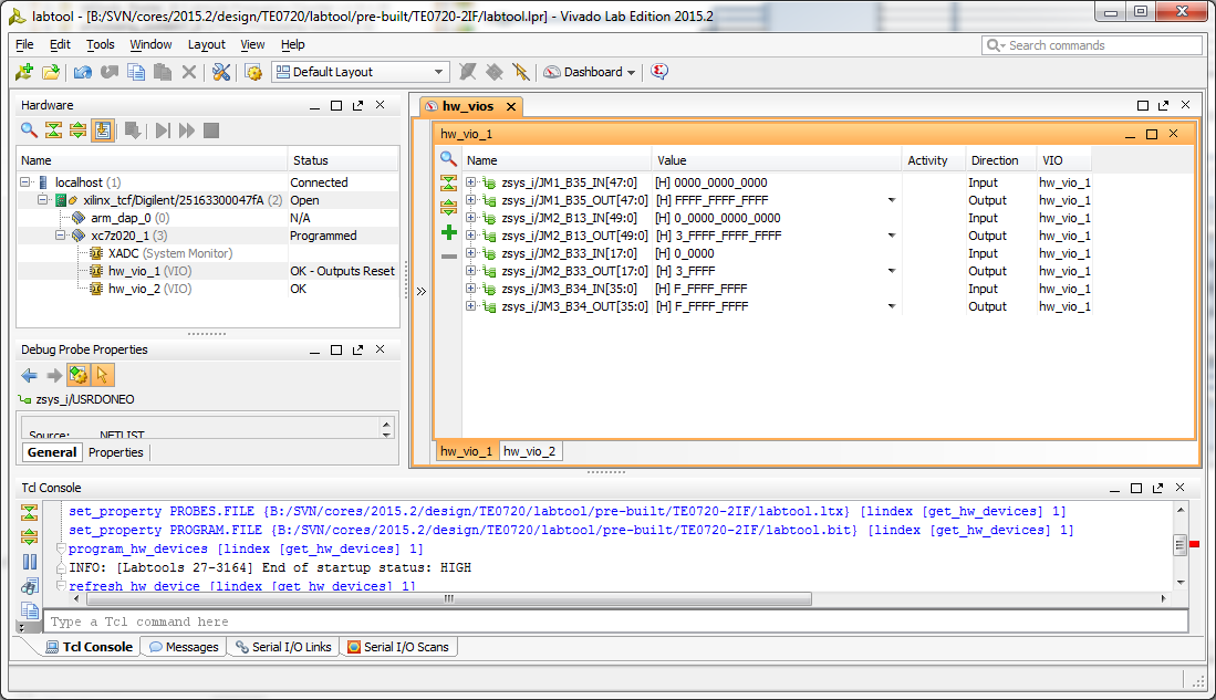
B2B I/O Pins: TE0720 is on TE0703 baseboard with no user specified VCCIO supplied for banks B13, B33, B35 - unpowered banks Read Inputs as 0 (despite the IO pullups), only B34 reads inputs as high as this bank is powered (J5 is set on TE0703)
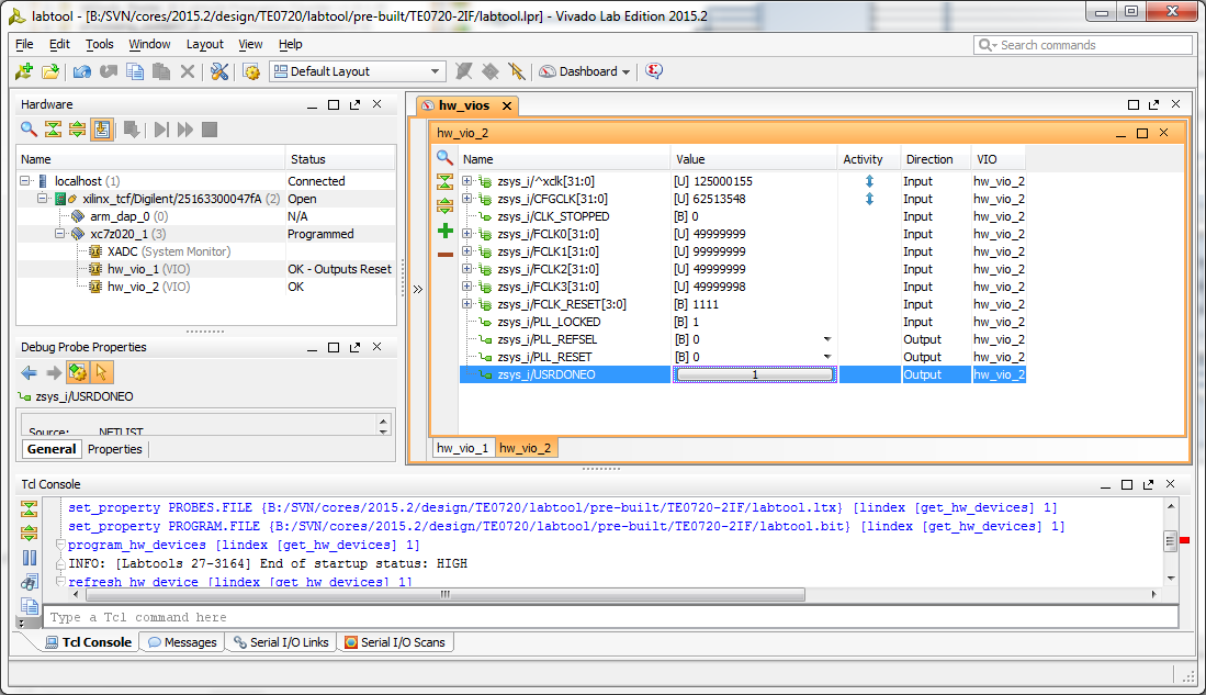
Clock measurements: 125MHz is Clock from Ethernet PHY, CFGCLK is FPGA internal configuration clock (nominal frequency 66MHz). TE0720 has no fixed PL clock sources, so the labtools design uses free running clock for all VIO's and PS supplied clock FCLK0 or FCLK3 as reference clock (it can be selected by changing PLL_REFSEL to 1 for FCLK0).
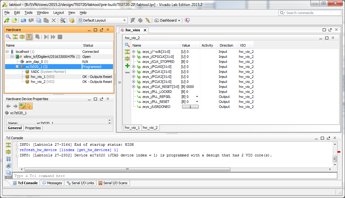
If the PS subsystem has executed FSBL (or it failed) then there are no clocks from PS, also the FCLK_RESET read as 0, this is indication that PS is not running at all.
TE0723
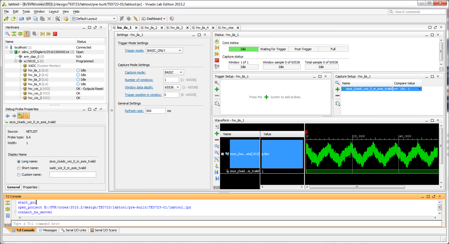
Reading analog values from XADC (50Hz noise visible)
Overview
Content Tools