Page History
| HTML |
|---|
<!--
Template Revision 1.64
(HTML comments will be not displayed in the document, no need to remove them. For Template/Skeleton changes, increase Template Revision number. So we can check faster, if the TRM style is up to date).
--> |
| HTML |
|---|
<!--
General Notes:
If some section is CPLD firmware dependent, make a note and if available link to the CPLD firmware description. It's in the TE shop download area in the corresponding module -> revision -> firmware folder.
--> |
| HTML |
|---|
<!--
General Notes:
Designate all graphics and pictures with a number and a description. For example "Figure 1: TE07xx-xx Block Diagram" or "Table 1: Initial delivery state". "Figure x" and "Table x" have to be formatted to bold.
--> |
| Scroll pdf ignore | |
|---|---|
Table of Contents
|
Overview
| Scroll Only (inline) |
|---|
https://wiki.trenz-electronic.de/display/PD/TEI0004+TRM for the current online version of this manual and other available documentation.
|
Arrow USB Programmer2 is an FT2232H based JTAG Adapter supported by Intel Quartus.
Key Features
- Supported by Intel Quartus (JTAG Mode only)
- Intel JTAG Compatible Pinout
- Additional UART Channel available
- Based on FTDI FT2232H USB2 Interface
- Micro USB Connector
- RED activity LED
- GREEN Power-on LED
Block Diagram
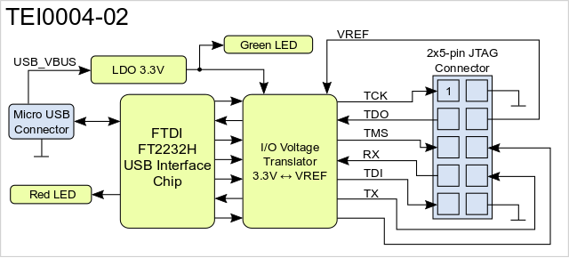
Figure 1: TEI0004-02 Block Diagram.
Main Components
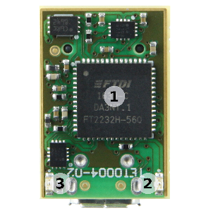
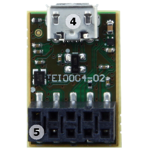
Figure 2: TEI0004-02 main components.
- FTDI FT2232H IC
- RED LED (Activity)
- Green LED (Power-on)
- Micro USB2 Connector
- 2x5-pin JTAG Connector (White dot marks Pin 1)
Signals, Interfaces and Pins
JTAG Connector Pinout
The 2x5 female socket have to be connected to the corresponding pin header on the target system. The signal assignment of the pin header on the adapter board is fully compatible to original USB blaster. Furthermore there is also an UART interface available and I/O-pin reserved for future use.
Following table describes the pin-assignment to the signals of the interfaces:
| Signal | Pin Number | Pin Number | Signal |
|---|---|---|---|
| TCK (output from adapter) | 1 | 2 | GND |
| TDO (input to adapter) | 3 | 4 | Reference I/O-voltage from target board for JTAG and UART |
| TMS (output from adapter) | 5 | 6 | Reserved Output (May be used as Processor Reset in future software releases) |
| UART RX (input to adapter) | 7 | 8 | UART TX (output from adapter) |
| TDI (output from adapter) | 9 | 10 | GND |
Table 1: JTAG Connector pin assignment.
USB Interface
The USB interface is provided by the FTDI FT2232H IC. The entire USB protocol is handled on chip and compatible to USB 2.0 High Speed (480 MBps) and Full Speed (12 MBps).
On-board Peripherals
FTDI FT2232H IC
FTDI FT2232H IC Channel A is used in MPPSE Mode for JTAG, Channel B is available as UART. FT2232H EEPROM is programmed with Arrow Programmer2 Identificator to be recognized by the support library for Quartus.
On-board LEDs
On-board LEDs indicating power-on and JTAG activity:
| Color | Description |
|---|---|
| Green | Power-on LED |
| Red | JTAG activity |
Table 2: On-board LEDs.
Power
Power supply of the adapter board
Arrow Programmer2 is powered via USB.
Technical Specifications
Absolute Maximum Ratings
| Parameter | Min | Max | Units | Reference Document |
|---|---|---|---|---|
VREF | -0.5 | 4.6 | V | Nexperia 74AVCH4T245 data sheet |
| USB VBUS | 4.75 | 5.25 | V | USB 2.0 Specification |
| Voltage on I/O pins | -0.5 | 4.6 | V | Nexperia 74AVCH4T245 data sheet |
| Storage temperature | -40 | +90 | °C | LED 19-213/R6C-AL1M2VY/3T data sheet |
Table 3: Absolute maximum ratings.
Recommended Operating Conditions
| Parameter | Min | Max | Units | Reference Document |
|---|---|---|---|---|
VREF | 0.8 | 3.6 | V | Nexperia 74AVCH4T245 data sheet |
| USB VBUS | 4.75 | 5.25 | V | USB 2.0 Specification |
| Voltage on I/O pins | 0 | VREF | V | Nexperia 74AVCH4T245 data sheet |
| Operating temperature | -40 | +85 | °C | FTDI FT2232H data sheet |
Table 4: Recommended operating conditions.
Operating Temperature Range
Industrial grade: -40°C to +85°C.
Arrow Programmer2 can be used within industrial temperature range.
Physical Dimensions
Module size: 14.2mm × 20.8mm. Please download the assembly diagram for exact numbers.
Highest part on PCB: 7.37 mm. Please download the step model for exact numbers.
All dimensions are given in millimeters and mil.
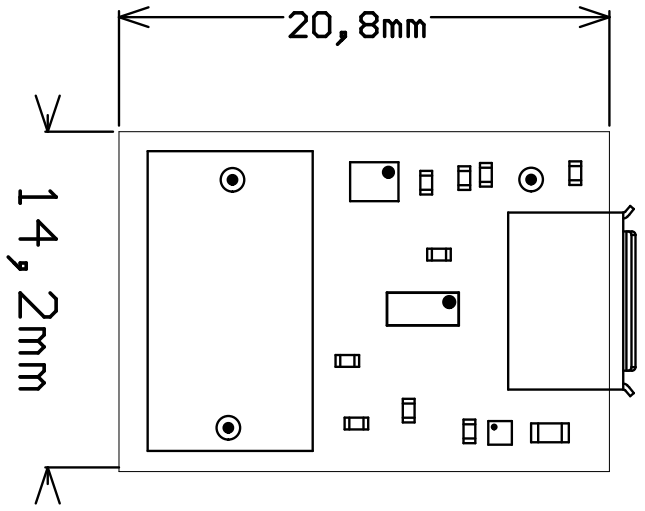
Figure 3: Physical dimensions drawing.
Revision History
Hardware Revision History
| Date | Revision | Notes | PCN | Documentation Link |
|---|---|---|---|---|
| - | 01 | Prototypes | - | - |
| - | 02 | First production release. | - | TEI0004 |
Table 5: Hardware revision history.
Hardware revision number can be found on the PCB board together with the module model number separated by the dash.
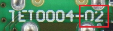
Figure 4: Revision number.
Document Change History
| HTML |
|---|
<!--
Generate new entry:
1.add new row below first
2.Copy "Page Information Macro(date)" Macro-Preview, Metadata Version number, Author Name and description to the empty row. Important Revision number must be the same as the Wiki document revision number
3.Update Metadata = "Page Information Macro (current-version)" Preview+1 and add Author and change description.
--> |
Date | Revision | Contributors | Description | ||||||||||||||||||||||||||
|---|---|---|---|---|---|---|---|---|---|---|---|---|---|---|---|---|---|---|---|---|---|---|---|---|---|---|---|---|---|
|
|
|
| ||||||||||||||||||||||||||
2022-05-05 | v.50 | John Hartfiel |
| ||||||||||||||||||||||||||
| 2017-11-23 | v.31 | Ali Naseri | updated block diagram | ||||||||||||||||||||||||||
2017-11-21 | v.25 | Ali Naseri |
|
Table 6: Document change history.
Disclaimer
| Include Page | ||||
|---|---|---|---|---|
|
...
Pin 10,
11
...
Pin 151,
153, 155,
157, 159
...
Pin 138,
140, 142,
144, 153,
154, 155,
156, 157,
158, 159,
160
...
Pin 157,
158, 159,
160
...
Pin A9,
A10, B8,
B10
...
connector
...
Overview
Content Tools