Page History
| HTML |
|---|
<!--
Template Revision 1.4.1 (modified)
Basic Notes
 - export PDF to download, if vivado revision is changed!
 - Template is for different design and SDSoC and examples, remove unused or wrong description!
--> |
...
| HTML |
|---|
<!-- Add Basic Key Features of the design (should be tested) --> |
| Excerpt |
|---|
|
Revision History
| HTML |
|---|
<!-- - Add changes from design - Export PDF to download, if vivado revision is changed! --> |
| Date | Vivado | Project Built | Authors | Description |
|---|---|---|---|---|
| 2018-0108-3127 | 2017.1 | TE0706_zsys_SDSoC_EDDP_FOC-vivado_2017.1-build_05_20180827095117.zip | UTIA | initial release |
Release Notes and Know Issues
...
| Module Model | Board Part Short Name | PCB Revision Support | DDR | QSPI Flash | Others | Notes |
|---|---|---|---|---|---|---|
| TE0720-03-2IF | TE0720_2IF | REV03 | 1 GB | 32 | ||
| TE0720-03-l1if | TE0720-_L1IF | REV03 | 512MB (L) | 32 | ||
| TE0720-03-1CF | TE0720-_1CF | REV03 | 1 GB | 32 | ||
| TE0720-03-2EF | TE0720-_2EF | REV03 | 1 GB | 32 | ||
| TE0720-03-07S | TE0720-_07S | REV03 | 1 GB (L) | 32 |
Design supports following carriers:
...
For general structure and of the reference design, see Project Delivery - AMD devices
Design Sources
| Type | Location | Notes |
|---|---|---|
| Vivado | <design name>/block_design <design name>/constraints <design name>/ip_lib | Vivado Project will be generated by TE Scripts |
| SDK/HSI | <design name>/sw_lib | Additional Software Template for SDK/HSI and apps_list.csv with settings for HSI |
| PetaLinux | <design name>/os/petalinux | PetaLinux template with current configuration |
| SDSoC | <design name>/../SDSoC_PFM | SDSoC Platform will be generated by TE Scripts or as separate download |
Additional Sources
| Type | Location | Notes |
|---|---|---|
...
Reference Design is available on:
Hardware Setup
...
TE0706_zsys_SDSoC_EDDP_FOC 2017.1 Platform with TEC0053-04 - EDPS Power Stage
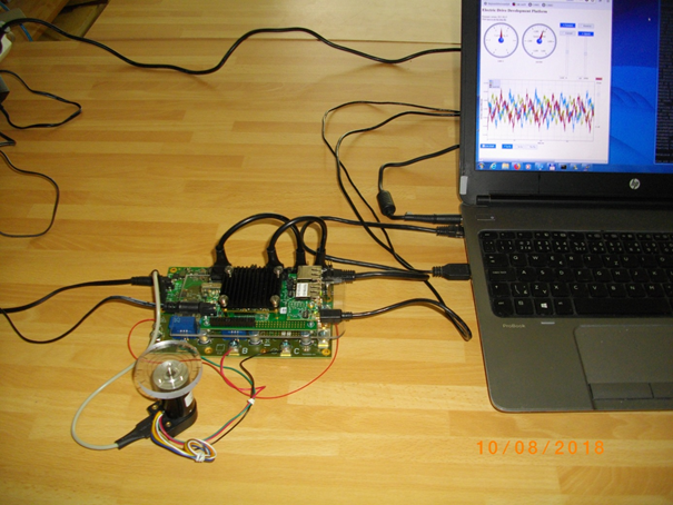
3-phase brush-less DC motor control with field oriented control (FOC) algorithm implemented in SDSoC 2017.1 on TE0720 module and TE0706-02 carrier board. The TEC0053-04 - EDPS Power Stage controls the BLDC motor with mounted encoder.
How to setup hardware shown in the figure above is described in following steps:
...
On TE0706-02 carrier board, use jumpers J10, J11 and J12 to select 3.3V:
Jumper Settings J10 Short 2-3 J11 Short 2-3 J12 Short 2-3 On TE0706-02 carrier board, set switch set switch S1 to:
Switch Settings S1_1 OFF S1_2 OFF S1_3 OFF S1_4 ON On TE0790-02 XMOD FTDI JTAG Adapter of the TE0706-02 board, set switch S2 to:
Switch Settings S2_1 ON S2_2 OFF S2_3 ON S2_4 OFF Info title IMPORTANT Before connecting to TEC0053-04 by PMOD 12pin cables, power on the TE0706-02 (NOTE: 5V!) and measure presence of 3.3V voltage on the TE0706-02 connector J5 pins: J5:5, J5:6, J5:45, J5:46.
Connection of motor rotation encoder
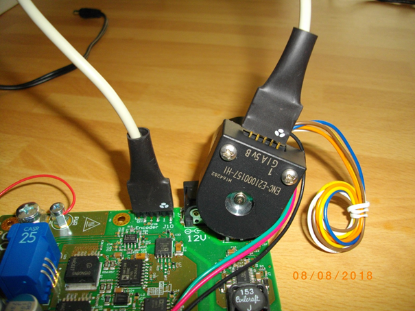
Motor rotation encoder is connected to the TEC0053-04 - EDPS Power Stage Pmod 6 pin cable connector kit. See the orientation and position of the 5 wire connection. There are 6 pins on the TEC0053-04 board. There are only 5 pins on the motor encoder. Pin 1 connects to pin 1. 6-th wire is unconnected on the motor encoder side.
3-phase of the motor phase wires are connected to the TEC0053-04 Power Stage points A, B, C: A: green wire; B: red wire; C: black wire.
All other motor wires are unused.
The TEC0053-04 - EDPS Power Stage can be powered by 12 V from the power supply by separate wire connecting of the point labled “PWR” (see above) with the fused point labeled “+DC” (see the first picture).Connect TE0706 with TEC0053-04 by two PMOD 12-pin cables.
Code Block language perl title Description of connections of TE0706 with TEC0053-04 # First 12 pin PMOD cable # Connections of TEC0053 J17 with TE0706-02 J5 # TEC0053 # TE0706-02 # GND # J17:25 # J5:50 set_property PACKAGE_PIN G20 [get_ports {SCLK}]; # J17:23 # J5:48 # 3,3V # J17:21 # J5:46 set_property PACKAGE_PIN E21 [get_ports {SDI1}]; # J17:19 # J5:44 set_property PACKAGE_PIN B19 [get_ports {SDI2}]; # J17:17 # J5:42 set_property PACKAGE_PIN D20 [get_ports {SDI3}]; # J17:15 # J5:40 # GND # J17:26 # J5:49 set_property PACKAGE_PIN G21 [get_ports {SDV}]; # J17:24 # J5:47 # 3,3V # J17:22 # J5:45 set_property PACKAGE_PIN D21 [get_ports {ENC_A}]; # J17:20 # J5:43 set_property PACKAGE_PIN B20 [get_ports {ENC_B}]; # J17:18 # J5:41 set_property PACKAGE_PIN C20 [get_ports {ENC_I}]; # J17:16 # J5:39 # All signals connected by the first PMOD cable cable belong to TE0720 Zynq Bank 35. # Second 12 pin PMOD cable # Connections of TEC0053 J17 with TE0706-02 J5 # TEC0053 # TE0706-02 # GND # J17:1 # J5:2 # Not used in the design # J17:3 # J5:4 # 3,3V # J17:5 # J5:6 set_property PACKAGE_PIN W17 [get_ports {GH[2]}]; # J17:7 # J5:8 set_property PACKAGE_PIN W20 [get_ports {GH[1]}]; # J17:9 # J5:10 set_property PACKAGE_PIN AA16 [get_ports {GH[0]}]; # J17:11 # J5:12 # GND # J17:2 # J5:1 # Not used in the design # J17:4 # J5:3 # 3,3V # J17:6 # J5:5 set_property PACKAGE_PIN W18 [get_ports {GL[2]}]; # J17:8 # J5:7 set_property PACKAGE_PIN W21 [get_ports {GL[1]}]; # J17:10 # J5:9 set_property PACKAGE_PIN AB16 [get_ports {GL[0]}]; # J17:12 # J5:11 #All signals connected by the second PMOD cable belong to TE0720 Zynq Bank 33. # Second PMOD Cable 12-pin contains these two wires unconnected to the SDSoC design: # Unused connections of TEC0053 J17 with TE0706-02 J5 # TEC0053 # TE0706-02 #set_property PACKAGE_PIN W16 [get_ports {gpio_0_tri_io[1]}]; # J17:3 # J5:4 #set_property PACKAGE_PIN Y16 [get_ports {gpio_0_tri_io[0]}]; # J17:4 #J5:3
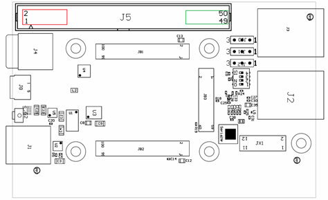
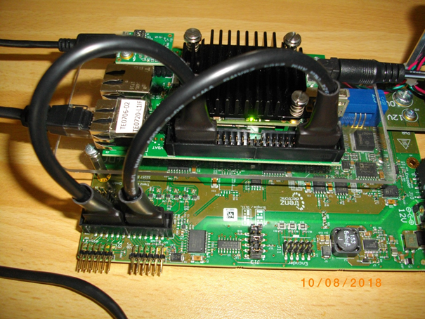
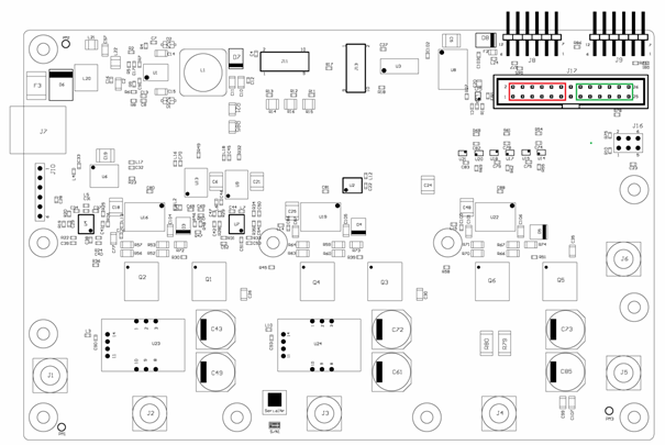
TE0706-02 carrier board has highlighted position of two 12 pin PMOD cables. Please take care, when connecting both cables to respect pin connections as listed above.
TEC0053-04 power stage board has highlighted position of two 12 pin PMOD cables.Info title IMPORTANT Wrong placement of the PMOD 12pin connects might result in a damaged electronic.
Design Setup
Launch
...
title IMPORTANT Wrong placement of the PMOD 12pin connects might result in a damaged electronic.
Design Setup
Create SDSoC Platform from TE Reference Design
- Unzip Reference Design
Do not change base folder name after extraction!
<install_path>\TE0706_zsys_SDSoC_EDDP_FOC\zsys\
CD to the directory and run from win terminal:
_create_win_setup.cmd
run from win terminal:
_use_virtual_drive.cmd
reply to select an virtual drive name (example X): X
reply: 0
cd X:\zsys
This is shortest possible path and directory name for building of the platform
in windows (to respect the 260 character limitations.)Info title NOTE Do not change the name of the directory /zsys
It has to be identical to the shortest possible platform name “zsys”
for the Zynq 7000 targets.Enable SDSOC, set install path of Xilinx tools, set your hardware assembly option in: "design_basic_settings.cmd" Select one of these supported modules (1,4,5,6,7):
ID TE Module 1 te0720-03-2if 4 te0720-03-l1if 5 te0720-03-1cf 6 te0720-03-2ef 7 te0720-03-07s Info title NOTE Selection 7 supports the TE0720-03-14S-1C module (xc7z014sclg484-1c device).
Create Reference Design: run "vivado_create_project_guimode.cmd"
VIVADO:
TCL-Console type: TE::hw_build_design -export_prebuilt
Find hardware handoff file .hdf under prebuilt folder abd copy it to Ubuntu 16.4, with Petalinux 2017.1.
Info title IMPORTANT The executable flag under Linux OS must be set for files:
./init_config.sh
./project-spec/meta-user/recipes-apps/libuv/files/checksparse.sh
./project-spec/meta-user/recipes-apps/libuv/files/gyp_uv.py
./project-spec/meta-user/recipes-apps/libuv/files/autogen.sh
./project-spec/meta-user/recipes-apps/libuv/files/android-configure
./project-spec/meta-user/recipes-apps/libuv/update-src.shIn Ubuntu 16.04, build Petalinux image image.ub and uboot u-boot.elf using Petalinux BSP provided under os folder and place new images to correct subfolder in prebuilt/os
- TCL-Console type: TE::sw_run_hsi
- TCL-Console type:TE::ADV::beta_util_sdsoc_project
Vivado project will be modified by copying constrain files locally to project.
Info title NOTE If needed, recreate project with batch file to restore original Vivado project with externally linked constrains.
Wait for project creation:
SDSoC Platform is created in
X:\zsys\SDSoC_PFM\<TE::SHORTDIR>\zsysCopy
X:\zsys\_use_virtual_drive.cmd
to
X: \SDSoC_PFM\<TE::SHORTDIR>\zsysCopy these two files from:
X:\zsys\init.sh
X:\zsys\focserver.conf
to
X:\SDSoC_PFM\<TE::SHORTDIR>\zsys\sw\linux\image\init.sh
X:\SDSoC_PFM\<TE::SHORTDIR>\zsys\sw\linux\image\focserver.confCopy directory with all files from:
X:\zsys\misc\src\
to
X: \SDSoC_PFM\<TE::SHORTDIR>\zsys\src\v. Copy directory with all files from:
X:\zsys\misc\sw\aarch32-linux\
X:\zsys\misc\sw\aarch32-none\
to
X: \SDSoC_PFM\<TE::SHORTDIR>\zsys\sw\aarch32-linux\
X: \SDSoC_PFM\<TE::SHORTDIR>\zsys\sw\ aarch32-none\
- Close current Vivado project
Clear working project files by script
X:\zsys\design_clear_design_folders.cmdFrom win terminal, execute:
_use_virtual_drive.cmd
reply to select an virtual drive name (example X): X
reply: 1
This will disconnect the virtual X: driveCompile support libraries serving for connection to 64bit AXI I/O.
Open the SDx Terminal 2017.1
CD to: <install_path>\TE0706_zsys_SDSoC_EDDP_FOC\SDSoC_PFM\<TE::SHORTDIR>\zsys\src\
In the SDx Terminal 2017.1, run batch file:
build_linux.bat
Library for the SDSoC Linux target is created:
<install_path>\TE0706_zsys_SDSoC_EDDP_FOC\SDSoC_PFM\<TE::SHORTDIR>\zsys\src\libte0720_foc.a
Move the created library libte0720_foc.a to
c:\TV71u\TE0706_zsys_SDSoC_EDDP_FOC\SDSoC_PFM\te0720_2if\zsys\sw\aarch32-linux\lib\libte0720_foc.a
Delete the created _sds directory
<install_path>\TE0706_zsys_SDSoC_EDDP_FOC\SDSoC_PFM\<TE::SHORTDIR>\zsys\src\_sdsIn the SDx Terminal 2017.1, run batch file:
build_standalone.bat
Library for the SDSoC standalone target is created:
<install_path>\TE0706_zsys_SDSoC_EDDP_FOC\SDSoC_PFM\<TE::SHORTDIR>\zsys\src\libte0720_foc.a
Move the created library libte0720_foc.a to
<install_path>\TE0706_zsys_SDSoC_EDDP_FOC\SDSoC_PFM\<TE::SHORTDIR>\\zsys\sw\aarch32-none\lib\ libte0720_foc.a
Delete the created _sds directory
<install_path>\TE0706_zsys_SDSoC_EDDP_FOC\SDSoC_PFM\<TE::SHORTDIR>\zsys\src\_sds
The SDSoC platform for the target \<TE::SHORTDIR> is in
<install_path>\TE0706_zsys_SDSoC_EDDP_FOC\SDSoC_PFM\<TE::SHORTDIR>Close the SDx Terminal 2017.1
Set TE SDSoC Platform as local SDSoC Platform
- Use the created SDSoC Platform for <TE::SHORTDIR> module present in the directory:
Open new windows terminal and CD to:
<install_path>\TE0706_zsys_SDSoC_EDDP_FOC\SDSoC_PFM\<TE::SHORTDIR> - From win terminal, run
_use_virtual_drive.cmd
reply to select an virtual drive name (example X): X
reply: 0
CD to:
X:\<TE::SHORTDIR>
This is shortest possible path and directory name for the SDSoC project working with the created SDSoC 2017.1 platform in the directory:
X:\<TE::SHORTDIR>\zsys
Create SDSoC Project
- Start SDSoC 2017.1 in the directory
- Select Workspace
X:\ <TE::SHORTDIR> - Click "Create SDSoC Project"
- Set Project Name (example: foc01)
- Set Platform:
- Others. Path to Project is:
X:\ <TE::SHORTDIR>\zsys - Select OS: Linux
- Click "Next"
- Select Template Application "focserver" "Field Oriented Control with Web UI"
- Click "Finished"
- Right click on the project -> C/C++ Build Settings
In the top level Configuration menu select [All configurations] - Add libraries 'te0720_foc' and 'dl' to the linker flags! -> SDS++ Linker -> Libraries
- Add path to directory with Linux version of the 'libte0720_foc.a' library! -> SDS++ Linker -> Libraries
Example for <TE::SHORTDIR> = te0720_2if:
"X:/te0720_2if/zsys/sw/aarch32-linux/lib" - Add path to directory with te0720_foc.h! -> SDSCC Compiler -> Directories
Example for <TE::SHORTDIR> = te0720_2if:
"X:/te0720_2if/zsys/sw/aarch32-linux/include" - Add path to directory with te0720_foc.h! -> SDS++ Compiler -> Directories
Example for <TE::SHORTDIR> = te0720_2if:
"X:/te0720_2if/zsys/sw/aarch32-linux/include" - In main SDx Project Settings:
unselect box [] Generate bitstream
unselect box [] Generate SD card image
these two unselections will accelerate the initial compilation of the platform, needed for creation of the final platform hdf file needed for generation of the final image.ub in the Petalinux 2017.1 under the Ubuntu. (cca 4 min instead of 30 min with these options selected).
The .hdf description of the foc01 HW design and related drivers is created in file (Example for <TE::SHORTDIR> = te0720_2if):
X:\te0720_2if\foc01\Debug\_sds\p0\ipi\zsys.sdk\zsys.hdf - Copy created file zsys.hdf to Petalinux 2017.1 in Ubuntu 16.04 and recompile the configuration of Petalinux with this .hdf file.
Result of this compilation is updated image.ub which includes device tree with the AXI-lite driver, created by the SDSoC initial compilation step. This driver is used by the focserver to set parameters of the HW accelerated SDSoC implementation of the FOC algorithm. - Replace the initial image.ub of the SDSoC platform with the created final image.ub by copy to (Example for <TE::SHORTDIR> = te0720_2if):
X:\te0720_2if\zsys\sw\linux\image\image.ub - In SDSoC, clear the foc01 project.
- In main SDx Project Settings:
select box [x] Generate bitstream
select box [x] Generate SD card image - Select Build project foc01
The SDSoC project is recompiled (cca 30 min) with foc01 integrated in HW.
SDCard image is created
Launch
- Copy created files to the SD card.
- ON PC, set the Ethernet address to 192.168.42.100
- Connect PC with Ethernet cable to the TE0706 board.
- Connect serial terminal via the USB cable.
- Power ON TEC0053-04 - EDPS Power Stage (12V).
- Power ON TE0706 board (12V).
- On PC, open serial terminal.
- Reset TE0705 board (by S2 button).
- Boot of Linux starts up to login stage. Login as 'root' with password 'root'.
To see top running processes, type
top
you can see running process
focserver - On PC, open www browser and connect to
http://192.168.42.123
to connect to the focserver running on the TE0720 module. - Use the WWW GUI to start and control the BLDC motor and to visualize data.
References
- SDSoC Environment - User Guide (UG1027)
- SDSoC Environment User Guide - An Instruction to SDSoC Environment (UG1028)
- SDSoC Environment User Guide - Platforms and Libraries (UG1146)
- EDDP Resources - Sources and documentation of the original EDDP Development kit
Appx. A: Change History and Legal Notices
...
| Date | Document Revision | Authors | Description | ||||||||||||||||||||||||
|---|---|---|---|---|---|---|---|---|---|---|---|---|---|---|---|---|---|---|---|---|---|---|---|---|---|---|---|
|
|
|
| ||||||||||||||||||||||||
| v.7 | UTIA |
| |||||||||||||||||||||||||
| 2018-08-15 | v.1 |
|
| ||||||||||||||||||||||||
| All |
|
...
Overview
Content Tools