Page History
...
| Scroll Title | ||||||||||||||||||||||||||||
|---|---|---|---|---|---|---|---|---|---|---|---|---|---|---|---|---|---|---|---|---|---|---|---|---|---|---|---|---|
| ||||||||||||||||||||||||||||
|
...
For general structure and of the reference design, see Project Delivery - AMD devices
Design Sources
| Scroll Title | |||||||||||||||||||||||||||||||||
|---|---|---|---|---|---|---|---|---|---|---|---|---|---|---|---|---|---|---|---|---|---|---|---|---|---|---|---|---|---|---|---|---|---|
| |||||||||||||||||||||||||||||||||
|
...
Trenz Electronic provides a tcl based built environment based on Xilinx Design Flow.
See also:
- Vivado/SDK/SDSoCAMD Development Tools#XilinxSoftware-BasicUserGuides
- Vivado Projects - TE Reference Design
- Project Delivery.
The Trenz Electronic FPGA Reference Designs are TCL-script based project. Command files for execution will be generated with "_create_win_setup.cmd" on Windows OS and "_create_linux_setup.sh" on Linux OS.
TE Scripts are only needed to generate the vivado project, all other additional steps are optional and can also executed by Xilinx Vivado/SDK GUI. For currently Scripts limitations on Win and Linux OS see: Project Delivery Currently limitations of functionality
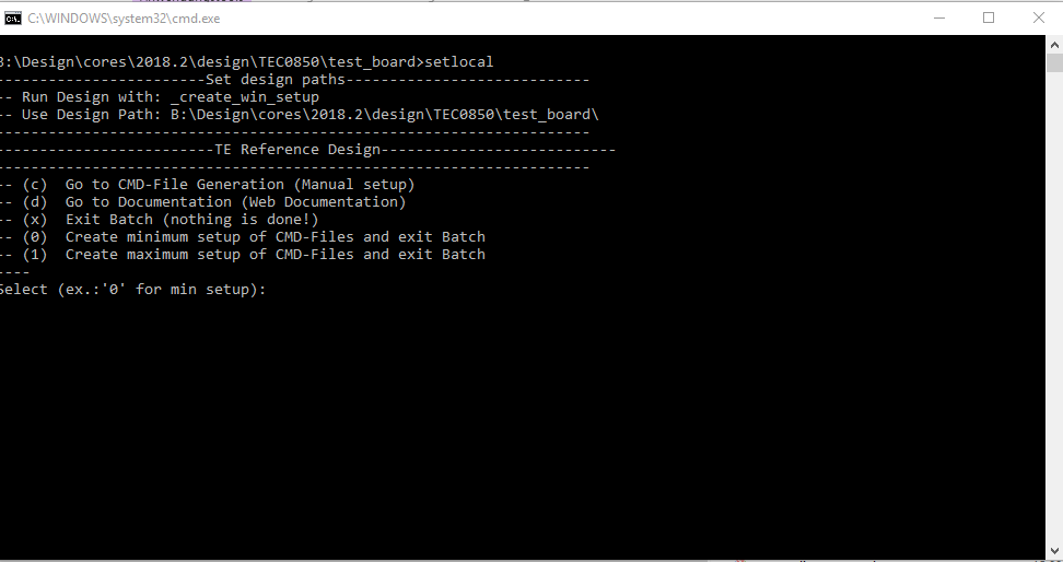
- _create_win_setup.cmd/_create_linux_setup.sh and follow instructions on shell:
- Press 0 and enter for minimum setup
- (optional Win OS) Generate Virtual Drive or use short directory for the reference design (for example x:\<design name>)
- Create Project
- Select correct device and Xilinx install path on "design_basic_settings.cmd" and create Vivado project with "vivado_create_project_guimode.cmd"
Note: Select correct one, see TE Board Part Files
- Select correct device and Xilinx install path on "design_basic_settings.cmd" and create Vivado project with "vivado_create_project_guimode.cmd"
- Create HDF and export to prebuilt folder
- Run on Vivado TCL: TE::hw_build_design -export_prebuilt
Note: Script generate design and export files into \prebuilt\hardware\<short dir>. Use GUI is the same, except file export to prebuilt folder
- Run on Vivado TCL: TE::hw_build_design -export_prebuilt
- Create Linux (uboot.elf and image.ub) with exported HDF
- HDF is exported to "prebuilt\hardware\<short name>"
Note: HW Export from Vivado GUI create another path as default workspace. - Create Linux images on VM, see PetaLinux KICKstart
- Use TE Template from /os/petalinux
Note: run init_config.sh before you start petalinux config. This will set correct temporary path variable.
- Use TE Template from /os/petalinux
- HDF is exported to "prebuilt\hardware\<short name>"
- Add Linux files (uboot.elf and image.ub) to prebuilt folder
- "prebuilt\os\petalinux\default" or "prebuilt\os\petalinux\<short name>"
Notes: Scripts select "prebuilt\os\petalinux\<short name>", if exist, otherwise "prebuilt\os\petalinux\default"
- "prebuilt\os\petalinux\default" or "prebuilt\os\petalinux\<short name>"
- Generate Programming Files with HSI/SDK
- Run on Vivado TCL: TE::sw_run_hsi
Note: Scripts generate applications and bootable files, which are defined in "sw_lib\apps_list.csv" - (alternative) Start SDK with Vivado GUI or start with TE Scripts on Vivado TCL: TE::sw_run_sdk
Note: See SDK Projects
- Run on Vivado TCL: TE::sw_run_hsi
...
Xilinx documentation for programming and debugging: Vivado/SDK/SDSoC-Xilinx Software Programming and Debugging
QSPI
Optional for Boot.bin on QSPI Flash and image.ub on SD.
...
| Page properties | ||||
|---|---|---|---|---|
| ||||
Note:
|
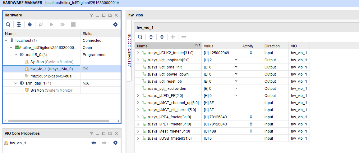
GTH Transceiver with Aurora IP:
- MGT Control: looback, PMA Init, Power Down, Reset... see: ug576-ultrascale-gth-transceivers
- Loopback 2 is Near-end PMA Loopback, if no lane is connected, 0 for normal operation
- Set PMA Init one time after changing
- Channel up is link status for the lanes
- PLL GTP lock status of GTH PLLs,
LED
- Control of front panel user LEDs
FMeter
- Measurement of different CLKs
- Note: USB CLK is only available if USB 3 is connected.
| Scroll Title | ||||
|---|---|---|---|---|
| ||||
System Design - Vivado
| Page properties | ||||
|---|---|---|---|---|
| ||||
Note:
|
...
| Code Block | ||
|---|---|---|
| ||
/include/ "system-conf.dtsi"
/ {
};

/* QSPI PHY */
&qspi {
    #address-cells = <1>;
    #size-cells = <0>;
    status = "okay";
    flash0: flash@0 {
        compatible = "jedec,spi-nor";
        reg = <0x0>;
        #address-cells = <1>;
        #size-cells = <1>;
    };
};

/* ETH PHY */

&gem0 {
    phy-handle = <&phy0>;
    phy0: phy0@1 {
        device_type = "ethernet-phy";
        reg = <1>;
    };
};


/* USB 2.0 */

&dwc3_0 {
    status = "okay";
    dr_mode = "host";
    maximum-speed = "high-speed";
    /delete-property/phy-names;
    /delete-property/phys;
    /delete-property/snps,usb3_lpm_capable;
};

&dwc3_1 {
    status = "okay";
    dr_mode = "host";
    maximum-speed = "high-speed";
    /delete-property/phy-names;
    /delete-property/phys;
    /delete-property/snps,usb3_lpm_capable;
};


/* SD*/

&sdhci1 {
    disable-wp;
    no-1-8-v;
};

/* SPI */
// &spi0 {
//     num-cs = <1>;
//     ext_command:spidev@0{
//         compatible="spidev";
//         reg = <0>; //chipselect 0
//         spi-max-frequency= <100000>;
//         spidev-name = "EXT";
//     };
// };
//

/* I2C */
// &i2c0 {
//     #address-cells = <1>;
//     #size-cells = <0>;
// };

&i2c1{  // TEC0850
    #address-cells = <1>;
    #size-cells = <0>;
    // Instantiate EEPROM driver
    eeprom153: eeprom@53 {
        compatible = "atmel,24c02";
        reg = <0x53>;
    };
    // Instantiate EEPROM driver
    eeprom150: eeprom@50 {
        compatible = "atmel,24c128";
        reg = <0x50>;
    };
    // There is also Clock generator chip
    // Si5345 at address 0x69, but there is
    // no standard driver in Linux kernel yet
};
|
Kernel
...
Deactivate:
CONFIG_CPU_IDLE (only needed to fix JTAG Debug issue)
CONFIG_CPU_FREQ (only needed to fix JTAG Debug issue)
Rootfs
Activate:
- i2c-tools
Applications
...

