Table of contents
Overview
ZynqMP PS Design with Linux example, simple frequency counter to some CLKs, MGT Aurora Test IP and USB 3 FTDI FIFO IP.
Refer to http://trenz.org/tec0850-info for the current online version of this manual and other available documentation.
Key Features
- PetaLinux
- SD
- ETH
- USB FIFO
- Aurora
- FMeter
- Modified FSBL for SI5345 programming
- Special FSBL for QSPI programming
Revision History
| Date | Vivado | Project Built | Authors | Description |
|---|---|---|---|---|
| 2018-09-13 | 2018.2 | TEC0850-test_board-vivado_2018.2-build_03_20180913143619.zip TEC0850-test_board_noprebuilt-vivado_2018.2-build_03_20180913143635.zip | Oleksandr Kiyenko, John Hartfiel | initial release |
Table 1: Design Revision History
Release Notes and Know Issues
| Issues | Description | Workaround | To be fixed version |
|---|---|---|---|
| No known issues | --- | --- | --- |
Table 2: Known Issues
Requirements
Software
| Software | Version | Note |
|---|---|---|
| Vivado | 2018.2 | needed |
| SDK | 2018.2 | needed |
| PetaLinux | 2018.2 | needed |
| SI5345 Clock Builder | --- | optional |
Table 3: Software
Hardware
Basic description of TE Board Part Files is available on TE Board Part Files.
Complete List is available on <design name>/board_files/*_board_files.csv
Design supports following modules:
| Module Model | Board Part Short Name | PCB Revision Support | DDR | QSPI Flash | Others | Notes |
|---|---|---|---|---|---|---|
| TEC0850-02-15EG-1E | 15eg_1e | REV02 | SODIMM, configured for 8GB: CT8G4SFS824A | 128MB |
Table 4: Hardware Modules
Design supports following carriers:
| Carrier Model | Notes |
|---|---|
CompactPCI compatible Backplanes | |
| standalone | separat 12V powersupply |
Table 5: Hardware Carrier
Additional HW Requirements:
| Additional Hardware | Notes |
|---|---|
Table 6: Additional Hardware
Content
For general structure and of the reference design, see Project Delivery - AMD devices
Design Sources
| Type | Location | Notes |
|---|---|---|
| Vivado | <design name>/block_design <design name>/constraints <design name>/ip_lib | Vivado Project will be generated by TE Scripts |
| SDK/HSI | <design name>/sw_lib | Additional Software Template for SDK/HSI and apps_list.csv with settings for HSI |
| PetaLinux | <design name>/os/petalinux | PetaLinux template with current configuration |
| SDSoC | <design name>/../SDSoC_PFM | SDSoC Platform will be generated by TE Scripts or as separate download |
Table 7: Design sources
Additional Sources
| Type | Location | Notes |
|---|---|---|
| SI5345 | <design name>/misc/Si5345 | SI5345 Project with current PLL Configuration |
Table 8: Additional design sources
Prebuilt
File | File-Extension | Description |
|---|---|---|
| BIF-File | *.bif | File with description to generate Bin-File |
| BIN-File | *.bin | Flash Configuration File with Boot-Image (Zynq-FPGAs) |
| BIT-File | *.bit | FPGA (PL Part) Configuration File |
| DebugProbes-File | *.ltx | Definition File for Vivado/Vivado Labtools Debugging Interface |
| Diverse Reports | --- | Report files in different formats |
| Hardware-Platform-Specification-Files | *.hdf | Exported Vivado Hardware Specification for SDK/HSI and PetaLinux |
| LabTools Project-File | *.lpr | Vivado Labtools Project File |
| OS-Image | *.ub | Image with Linux Kernel (On Petalinux optional with Devicetree and RAM-Disk) |
| Software-Application-File | *.elf | Software Application for Zynq or MicroBlaze Processor Systems |
Table 9: Prebuilt files
Download
Reference Design is only usable with the specified Vivado/SDK/PetaLinux/SDx version. Do never use different Versions of Xilinx Software for the same Project.
Reference Design is available on:
Design Flow
Reference Design is available with and without prebuilt files. It's recommended to use TE prebuilt files for first lunch.
Trenz Electronic provides a tcl based built environment based on Xilinx Design Flow.
See also:
- AMD Development Tools#XilinxSoftware-BasicUserGuides
- Vivado Projects - TE Reference Design
- Project Delivery.
The Trenz Electronic FPGA Reference Designs are TCL-script based project. Command files for execution will be generated with "_create_win_setup.cmd" on Windows OS and "_create_linux_setup.sh" on Linux OS.
TE Scripts are only needed to generate the vivado project, all other additional steps are optional and can also executed by Xilinx Vivado/SDK GUI. For currently Scripts limitations on Win and Linux OS see: Project Delivery Currently limitations of functionality
- _create_win_setup.cmd/_create_linux_setup.sh and follow instructions on shell:
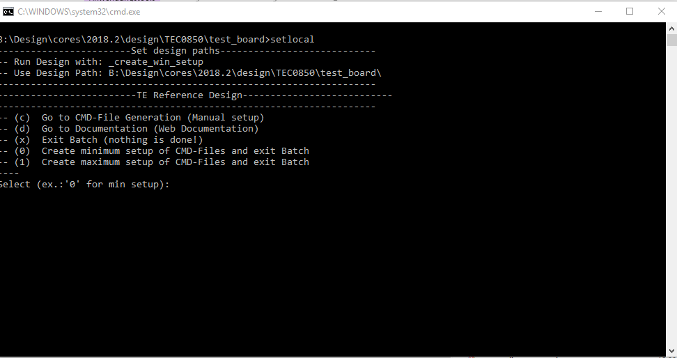
- Press 0 and enter for minimum setup
- (optional Win OS) Generate Virtual Drive or use short directory for the reference design (for example x:\<design name>)
- Create Project
- Select correct device and Xilinx install path on "design_basic_settings.cmd" and create Vivado project with "vivado_create_project_guimode.cmd"
Note: Select correct one, see TE Board Part Files
- Select correct device and Xilinx install path on "design_basic_settings.cmd" and create Vivado project with "vivado_create_project_guimode.cmd"
- Create HDF and export to prebuilt folder
- Run on Vivado TCL: TE::hw_build_design -export_prebuilt
Note: Script generate design and export files into \prebuilt\hardware\<short dir>. Use GUI is the same, except file export to prebuilt folder
- Run on Vivado TCL: TE::hw_build_design -export_prebuilt
- Create Linux (uboot.elf and image.ub) with exported HDF
- HDF is exported to "prebuilt\hardware\<short name>"
Note: HW Export from Vivado GUI create another path as default workspace. - Create Linux images on VM, see PetaLinux KICKstart
- Use TE Template from /os/petalinux
Note: run init_config.sh before you start petalinux config. This will set correct temporary path variable.
- Use TE Template from /os/petalinux
- HDF is exported to "prebuilt\hardware\<short name>"
- Add Linux files (uboot.elf and image.ub) to prebuilt folder
- "prebuilt\os\petalinux\default" or "prebuilt\os\petalinux\<short name>"
Notes: Scripts select "prebuilt\os\petalinux\<short name>", if exist, otherwise "prebuilt\os\petalinux\default"
- "prebuilt\os\petalinux\default" or "prebuilt\os\petalinux\<short name>"
- Generate Programming Files with HSI/SDK
- Run on Vivado TCL: TE::sw_run_hsi
Note: Scripts generate applications and bootable files, which are defined in "sw_lib\apps_list.csv" - (alternative) Start SDK with Vivado GUI or start with TE Scripts on Vivado TCL: TE::sw_run_sdk
Note: See SDK Projects
- Run on Vivado TCL: TE::sw_run_hsi
Launch
Programming
Check Module and Carrier TRMs for proper HW configuration before you try any design.
Xilinx documentation for programming and debugging: Vivado/SDK/SDSoC-Xilinx Software Programming and Debugging
QSPI
Optional for Boot.bin on QSPI Flash and image.ub on SD.
- Connect JTAG and power on carrier with module
- Open Vivado Project with "vivado_open_existing_project_guimode.cmd" or if not created, create with "vivado_create_project_guimode.cmd"
- Type on Vivado TCL Console: TE::pr_program_flash_binfile -swapp u-boot
Note: To program with SDK/Vivado GUI, use special FSBL (zynqmp_fsbl_flash) on setup
optional "TE::pr_program_flash_binfile -swapp hello_tec0850" possible - Copy image.ub on SD-Card
- For correct prebuilt file location, see <design_name>/prebuilt/readme_file_location.txt
- Insert SD-Card
SD
- Copy image.ub and Boot.bin on SD-Card.
- For correct prebuilt file location, see <design_name>/prebuilt/readme_file_location.txt
- Set Boot Mode to SD-Boot.
- Depends on Carrier, see carrier TRM.
- Insert SD-Card in SD-Slot.
JTAG
Not used on this Example.
Usage
- Prepare HW like described on section Programming
- Connect UART USB (most cases same as JTAG)
- Select SD Card as Boot Mode
Note: See TRM of the Carrier, which is used. - Power On PCB
Note: 1. ZynqMP Boot ROM loads PMU Firmware and FSBL from SD/QSPI Flash into OCM, 2. FSBL loads ATF(bl31.elf) and U-boot from SD into DDR, 3. U-boot load Linux from SD into DDR
Linux
- Open Serial Console (e.g. putty)
- Speed: 115200
- COM Port: Win OS, see device manager, Linux OS see dmesg |grep tty (UART is *USB1)
- Linux Console:
Note: Wait until Linux boot finished For Linux Login use:- User Name: root
- Password: root
- You can use Linux shell now.
- lsusb show USB controller → USB is connected to CIPIS connectors
- I2C devices: i2cdetect -y -r 0
- ETH0 works with udhcpc
Vivado HW Manager
GTH Transceiver with Aurora IP:
- MGT Control: looback, PMA Init, Power Down, Reset... see: ug576-ultrascale-gth-transceivers
- Loopback 2 is Near-end PMA Loopback, if no lane is connected, 0 for normal operation
- Set PMA Init one time after changing
- Channel up is link status for the lanes
- PLL GTP lock status of GTH PLLs,
LED
- Control of front panel user LEDs
FMeter
- Measurement of different CLKs
- Note: USB CLK is only available if USB 3 is connected.
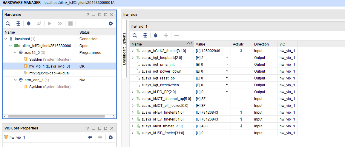
Figure 1: Vivado Hardware Manager
System Design - Vivado
Block Design
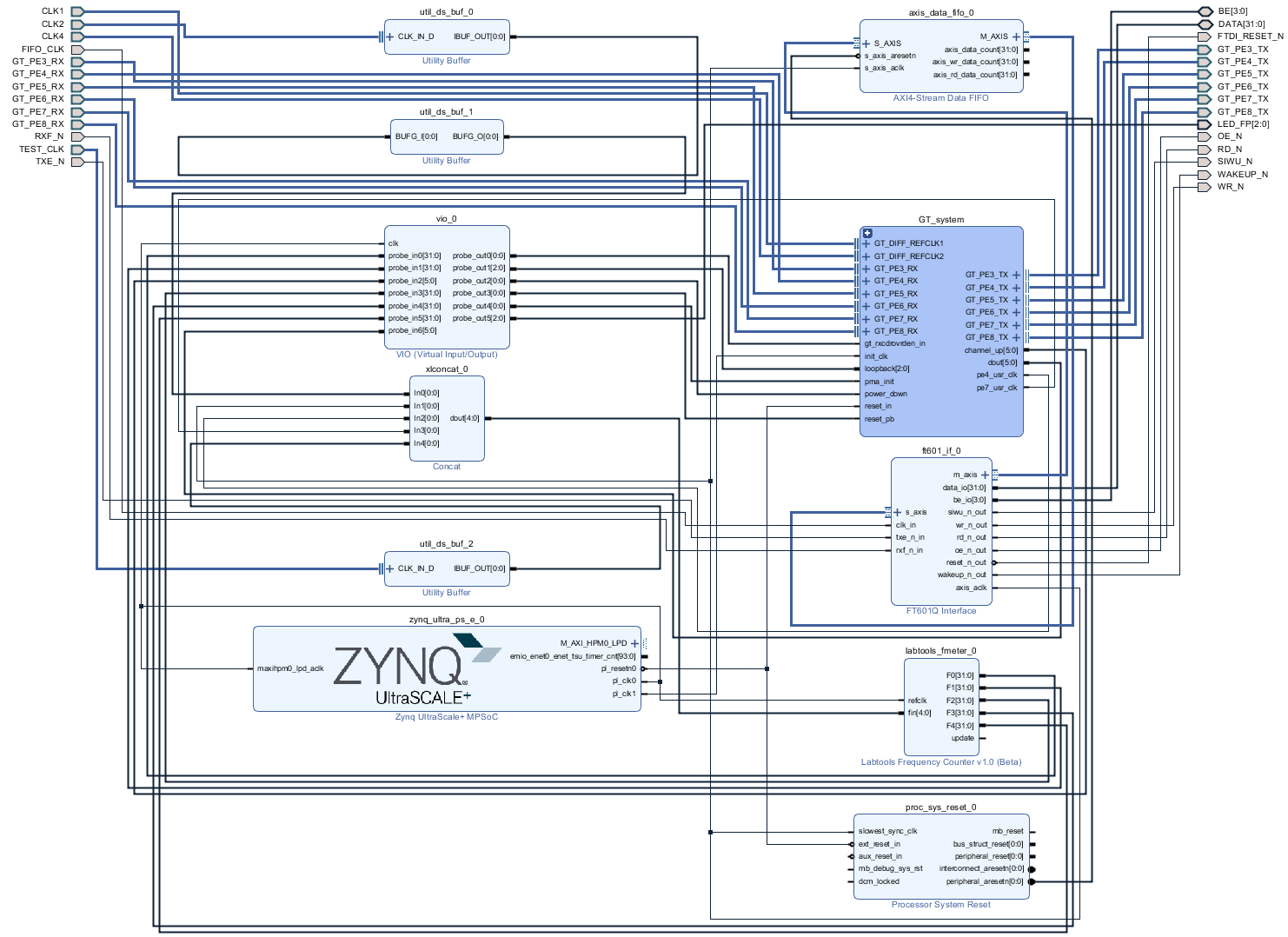
Figure 2: Block Design
PS Interfaces
| Type | Note |
|---|---|
| DDR | |
| QSPI | MIO |
| SD1 | MIO |
| I2C1 | MIO |
| UART0 | MIO |
| GPIO0..1 | MIO |
| SWDT0..1 | |
| TTC0..3 | |
| GEM0 | MIO |
| USB0 | MIO, USB2.0 |
| USB1 | MIO, USB2.0 |
Table 10: PS Interfaces
Constrains
Basic module constrains
_i_bitgen_common.xdc
set_property BITSTREAM.GENERAL.COMPRESS TRUE [current_design]
set_property BITSTREAM.CONFIG.UNUSEDPIN PULLNONE [current_design]
Design specific constrain
_i_tec0850_io.xdc
create_clock -period 12.800 -name GT_CLK1 [get_nets zusys_i/GT_system/aurora_m_left_0/inst/clock_module_i/ultrascale_tx_userclk_1/user_clk_out]
create_clock -period 12.800 -name GT_CLK2 [get_nets zusys_i/GT_system/aurora_m_right_0/inst/clock_module_i/ultrascale_tx_userclk_1/user_clk_out]
create_clock -period 12.800 -name GT_CLK3 [get_nets zusys_i/GT_system/aurora_s_left_1/inst/clock_module_i/ultrascale_tx_userclk_1/user_clk_out]
create_clock -period 12.800 -name GT_CLK4 [get_nets zusys_i/GT_system/aurora_s_left_2/inst/clock_module_i/ultrascale_tx_userclk_1/user_clk_out]
create_clock -period 12.800 -name GT_CLK5 [get_nets zusys_i/GT_system/aurora_s_right_1/inst/clock_module_i/ultrascale_tx_userclk_1/user_clk_out]
create_clock -period 12.800 -name GT_CLK6 [get_nets zusys_i/GT_system/aurora_s_right_2/inst/clock_module_i/ultrascale_tx_userclk_1/user_clk_out]


# Test
set_property PACKAGE_PIN W7 [get_ports {TEST_CLK_clk_p[0]}]
set_property PACKAGE_PIN W6 [get_ports {TEST_CLK_clk_p[0]}]
set_property IOSTANDARD LVDS [get_ports TEST_CLK_clk_*]

# Bank 44 HD 3.3V

set_property PACKAGE_PIN AF15 [get_ports {LED_FP[0]}]
set_property PACKAGE_PIN AG15 [get_ports {LED_FP[1]}]
set_property PACKAGE_PIN AE15 [get_ports {LED_FP[2]}]
set_property IOSTANDARD LVCMOS33 [get_ports LED_FP*]

# Bank 50 HD 3.3V
#set_property PACKAGE_PIN H11 [get_ports {DAC1_CLK}]
#set_property PACKAGE_PIN F10 [get_ports {DAC1_MODE[0]}]
#set_property PACKAGE_PIN D11 [get_ports {DAC1_D[0]}]
#set_property PACKAGE_PIN D10 [get_ports {DAC1_D[1]}]
#set_property PACKAGE_PIN G11 [get_ports {DAC1_D[2]}]
#set_property PACKAGE_PIN J11 [get_ports {DAC1_D[3]}]
#set_property PACKAGE_PIN G10 [get_ports {DAC1_D[4]}]
#set_property PACKAGE_PIN H10 [get_ports {DAC1_D[5]}]
#set_property PACKAGE_PIN J10 [get_ports {DAC1_D[6]}]
#set_property PACKAGE_PIN E10 [get_ports {DAC1_D[7]}]
#set_property IOSTANDARD LVCMOS33 [get_ports DAC1_*]

#set_property PACKAGE_PIN F12 [get_ports {DAC2_CLK}]
#set_property PACKAGE_PIN F11 [get_ports {DAC2_MODE[0]}]
#set_property PACKAGE_PIN G15 [get_ports {DAC2_D[0]}]
#set_property PACKAGE_PIN H14 [get_ports {DAC2_D[1]}]
#set_property PACKAGE_PIN J14 [get_ports {DAC2_D[2]}]
#set_property PACKAGE_PIN G14 [get_ports {DAC2_D[3]}]
#set_property PACKAGE_PIN G13 [get_ports {DAC2_D[4]}]
#set_property PACKAGE_PIN H13 [get_ports {DAC2_D[5]}]
#set_property PACKAGE_PIN H12 [get_ports {DAC2_D[6]}]
#set_property PACKAGE_PIN J12 [get_ports {DAC2_D[7]}]
#set_property IOSTANDARD LVCMOS33 [get_ports DAC2_*]

# Bank 44 HD 3.3V
#set_property PACKAGE_PIN AK15 [get_ports {DAC3_CLK}]
#set_property PACKAGE_PIN AK14 [get_ports {DAC3_MODE[0]}]
#set_property PACKAGE_PIN AG14 [get_ports {DAC3_D[0]}]
#set_property PACKAGE_PIN AE13 [get_ports {DAC3_D[1]}]
#set_property PACKAGE_PIN AG13 [get_ports {DAC3_D[2]}]
#set_property PACKAGE_PIN AJ15 [get_ports {DAC3_D[3]}]
#set_property PACKAGE_PIN AJ14 [get_ports {DAC3_D[4]}]
#set_property PACKAGE_PIN AH14 [get_ports {DAC3_D[5]}]
#set_property PACKAGE_PIN AF13 [get_ports {DAC3_D[6]}]
#set_property PACKAGE_PIN AH13 [get_ports {DAC3_D[7]}]
#set_property IOSTANDARD LVCMOS33 [get_ports DAC3_*]

#set_property PACKAGE_PIN AL12 [get_ports {DAC4_CLK}]
#set_property PACKAGE_PIN AK13 [get_ports {DAC4_MODE[0]}]
#set_property PACKAGE_PIN AP14 [get_ports {DAC4_D[0]}]
#set_property PACKAGE_PIN AN14 [get_ports {DAC4_D[1]}]
#set_property PACKAGE_PIN AM14 [get_ports {DAC4_D[2]}]
#set_property PACKAGE_PIN AN13 [get_ports {DAC4_D[3]}]
#set_property PACKAGE_PIN AP12 [get_ports {DAC4_D[4]}]
#set_property PACKAGE_PIN AN12 [get_ports {DAC4_D[5]}]
#set_property PACKAGE_PIN AL13 [get_ports {DAC4_D[6]}]
#set_property PACKAGE_PIN AM13 [get_ports {DAC4_D[7]}]
#set_property IOSTANDARD LVCMOS33 [get_ports DAC4_*]

# Bank 64 HP 1.8V
set_property PACKAGE_PIN AL6 [get_ports FIFO_CLK]
set_property IOSTANDARD LVCMOS18 [get_ports FIFO_CLK]
set_property PACKAGE_PIN AM8 [get_ports {FTDI_RESET_N}]
set_property IOSTANDARD LVCMOS18 [get_ports {FTDI_RESET_N}]
set_property PACKAGE_PIN AN8 [get_ports {WAKEUP_N}]
set_property IOSTANDARD LVCMOS18 [get_ports {WAKEUP_N}]

set_property PACKAGE_PIN AJ12 [get_ports {RXF_N}]
set_property IOSTANDARD LVCMOS18 [get_ports {RXF_N}]
set_property PACKAGE_PIN AK12 [get_ports {TXE_N}]
set_property IOSTANDARD LVCMOS18 [get_ports {TXE_N}]
set_property PACKAGE_PIN AM10 [get_ports {BE[0]}]
set_property PACKAGE_PIN AK10 [get_ports {BE[1]}]
set_property PACKAGE_PIN AM11 [get_ports {BE[2]}]
set_property PACKAGE_PIN AL11 [get_ports {BE[3]}]
set_property IOSTANDARD LVCMOS18 [get_ports {BE[*]}]
set_property PACKAGE_PIN AL10 [get_ports {SIWU_N}]
set_property IOSTANDARD LVCMOS18 [get_ports {SIWU_N}]
set_property PACKAGE_PIN AM9 [get_ports {WR_N}]
set_property IOSTANDARD LVCMOS18 [get_ports {WR_N}]
set_property PACKAGE_PIN AK9 [get_ports {RD_N}]
set_property IOSTANDARD LVCMOS18 [get_ports {RD_N}]
set_property PACKAGE_PIN AL8 [get_ports {OE_N}]
set_property IOSTANDARD LVCMOS18 [get_ports {OE_N}]

set_property PACKAGE_PIN AK1  [get_ports {DATA[0]}]
set_property PACKAGE_PIN AJ10 [get_ports {DATA[1]}]
set_property PACKAGE_PIN AJ9  [get_ports {DATA[2]}]
set_property PACKAGE_PIN AK7  [get_ports {DATA[3]}]
set_property PACKAGE_PIN AK5  [get_ports {DATA[4]}]
set_property PACKAGE_PIN AM1  [get_ports {DATA[5]}]
set_property PACKAGE_PIN AL2  [get_ports {DATA[6]}]
set_property PACKAGE_PIN AK4  [get_ports {DATA[7]}]
set_property PACKAGE_PIN AN1  [get_ports {DATA[8]}]
set_property PACKAGE_PIN AL3  [get_ports {DATA[9]}]
set_property PACKAGE_PIN AK8  [get_ports {DATA[10]}]
set_property PACKAGE_PIN AN2  [get_ports {DATA[11]}]
set_property PACKAGE_PIN AP2  [get_ports {DATA[12]}]
set_property PACKAGE_PIN AL7  [get_ports {DATA[13]}]
set_property PACKAGE_PIN AL5  [get_ports {DATA[14]}]
set_property PACKAGE_PIN AM4  [get_ports {DATA[15]}]
set_property PACKAGE_PIN AN4  [get_ports {DATA[16]}]
set_property PACKAGE_PIN AM5  [get_ports {DATA[17]}]
set_property PACKAGE_PIN AM6  [get_ports {DATA[18]}]
set_property PACKAGE_PIN AN3  [get_ports {DATA[19]}]
set_property PACKAGE_PIN AP3  [get_ports {DATA[20]}]
set_property PACKAGE_PIN AP4  [get_ports {DATA[21]}]
set_property PACKAGE_PIN AP5  [get_ports {DATA[22]}]
set_property PACKAGE_PIN AN6  [get_ports {DATA[23]}]
set_property PACKAGE_PIN AN7  [get_ports {DATA[24]}]
set_property PACKAGE_PIN AP6  [get_ports {DATA[25]}]
set_property PACKAGE_PIN AP7  [get_ports {DATA[26]}]
set_property PACKAGE_PIN AP11 [get_ports {DATA[27]}]
set_property PACKAGE_PIN AP10 [get_ports {DATA[28]}]
set_property PACKAGE_PIN AP9  [get_ports {DATA[29]}]
set_property PACKAGE_PIN AN9  [get_ports {DATA[30]}]
set_property PACKAGE_PIN AP8  [get_ports {DATA[31]}]
set_property IOSTANDARD LVCMOS18 [get_ports {DATA[*]}]

# Bank 66 HP 1.8V
set_property PACKAGE_PIN Y8  [get_ports {CLK2_clk_p[0]}]
set_property IOSTANDARD LVDS [get_ports {CLK2_clk_p[0]}]
create_clock -period 8.000 -name CLK2 [get_ports {CLK2_clk_p[0]}]

# MGT
set_property PACKAGE_PIN L27 [get_ports {CLK4_clk_p}]
set_property PACKAGE_PIN G8  [get_ports {CLK1_clk_p}
Software Design - SDK/HSI
For SDK project creation, follow instructions from:
Application
Template location: ./sw_lib/sw_apps/
zynqmp_fsbl
TE modified 2018.2 FSBL
Changes:
- Si5345 Configuration,
- see xfsbl_board.c, xfsbl_board.h, xfsbl_main.c
- Add register_map.h, si5345.c, si5345.h
Note: Remove compiler flags "-Os -flto -ffat-lto-objects" on 2018.2 SDK to generate FSBL
zynqmp_fsbl_flash
TE modified 2018.2 FSBL
Changes:
- Set FSBL Boot Mode to JTAG
- Disable Memory initialisation
- see xfsbl_initialisation.c, xfsbl_hw.h, xfsbl_handoff.c, xfsbl_main.c
Note: Remove compiler flags "-Os -flto -ffat-lto-objects" on 2018.2 SDK to generate FSBL
zynqmp_pmufw
Xilinx default PMU firmware.
hello_tec0850
Hello TEC0850 is a Xilinx Hello World example as endless loop instead of one console output.
u-boot
U-Boot.elf is generated with PetaLinux. SDK/HSI is used to generate Boot.bin.
Software Design - PetaLinux
For PetaLinux installation and project creation, follow instructions from:
Config
No changes.
U-Boot
#include <configs/platform-auto.h>
#define CONFIG_SYS_BOOTM_LEN 0xF000000

#define DFU_ALT_INFO_RAM \
                "dfu_ram_info=" \
        "setenv dfu_alt_info " \
        "image.ub ram $netstart 0x1e00000\0" \
        "dfu_ram=run dfu_ram_info && dfu 0 ram 0\0" \
        "thor_ram=run dfu_ram_info && thordown 0 ram 0\0"

#define DFU_ALT_INFO_MMC \
        "dfu_mmc_info=" \
        "set dfu_alt_info " \
        "${kernel_image} fat 0 1\\\\;" \
        "dfu_mmc=run dfu_mmc_info && dfu 0 mmc 0\0" \
        "thor_mmc=run dfu_mmc_info && thordown 0 mmc 0\0"

/*Required for uartless designs */
#ifndef CONFIG_BAUDRATE
#define CONFIG_BAUDRATE 115200
#ifdef CONFIG_DEBUG_UART
#undef CONFIG_DEBUG_UART
#endif
#endif

/*Define CONFIG_ZYNQMP_EEPROM here and its necessaries in u-boot menuconfig if you had EEPROM memory. */
#ifdef CONFIG_ZYNQMP_EEPROM
#define CONFIG_SYS_I2C_EEPROM_ADDR_LEN  1
#define CONFIG_CMD_EEPROM
#define CONFIG_ZYNQ_EEPROM_BUS          5
#define CONFIG_ZYNQ_GEM_EEPROM_ADDR     0x54
#define CONFIG_ZYNQ_GEM_I2C_MAC_OFFSET  0x20
#endif
Device Tree
/include/ "system-conf.dtsi"
/ {
};

/* QSPI PHY */
&qspi {
    #address-cells = <1>;
    #size-cells = <0>;
    status = "okay";
    flash0: flash@0 {
        compatible = "jedec,spi-nor";
        reg = <0x0>;
        #address-cells = <1>;
        #size-cells = <1>;
    };
};

/* ETH PHY */

&gem0 {
    phy-handle = <&phy0>;
    phy0: phy0@1 {
        device_type = "ethernet-phy";
        reg = <1>;
    };
};


/* USB 2.0 */

&dwc3_0 {
    status = "okay";
    dr_mode = "host";
    maximum-speed = "high-speed";
    /delete-property/phy-names;
    /delete-property/phys;
    /delete-property/snps,usb3_lpm_capable;
};

&dwc3_1 {
    status = "okay";
    dr_mode = "host";
    maximum-speed = "high-speed";
    /delete-property/phy-names;
    /delete-property/phys;
    /delete-property/snps,usb3_lpm_capable;
};


/* SD*/

&sdhci1 {
    disable-wp;
    no-1-8-v;
};

/* SPI */
// &spi0 {
//     num-cs = <1>;
//     ext_command:spidev@0{
//         compatible="spidev";
//         reg = <0>; //chipselect 0
//         spi-max-frequency= <100000>;
//         spidev-name = "EXT";
//     };
// };
//

/* I2C */
// &i2c0 {
//     #address-cells = <1>;
//     #size-cells = <0>;
// };

&i2c1{  // TEC0850
    #address-cells = <1>;
    #size-cells = <0>;
    // Instantiate EEPROM driver
    eeprom153: eeprom@53 {
        compatible = "atmel,24c02";
        reg = <0x53>;
    };
    // Instantiate EEPROM driver
    eeprom150: eeprom@50 {
        compatible = "atmel,24c128";
        reg = <0x50>;
    };
    // There is also Clock generator chip
    // Si5345 at address 0x69, but there is
    // no standard driver in Linux kernel yet
};
Kernel
Deactivate:
CONFIG_CPU_IDLE (only needed to fix JTAG Debug issue)
CONFIG_CPU_FREQ (only needed to fix JTAG Debug issue)
Rootfs
Activate:
- i2c-tools
Applications
startup
Script App to load init.sh from SD Card if available.
See: \os\petalinux\project-spec\meta-user\recipes-apps\startup\files
Additional Software
No additional software is needed.
SI5345
File location <design name>/misc/Si5345/RegisterMap.txt
General documentation how you work with these project will be available on Si5345
Appx. A: Change History and Legal Notices
Document Change History
To get content of older revision got to "Change History" of this page and select older document revision number.
| Date | Document Revision | Authors | Description |
|---|---|---|---|
| |||
| -- | all | -- |
Table x: Document change history.
Legal Notices
Data Privacy
Please also note our data protection declaration at https://www.trenz-electronic.de/en/Data-protection-Privacy
Document Warranty
The material contained in this document is provided “as is” and is subject to being changed at any time without notice. Trenz Electronic does not warrant the accuracy and completeness of the materials in this document. Further, to the maximum extent permitted by applicable law, Trenz Electronic disclaims all warranties, either express or implied, with regard to this document and any information contained herein, including but not limited to the implied warranties of merchantability, fitness for a particular purpose or non infringement of intellectual property. Trenz Electronic shall not be liable for errors or for incidental or consequential damages in connection with the furnishing, use, or performance of this document or of any information contained herein.
Limitation of Liability
In no event will Trenz Electronic, its suppliers, or other third parties mentioned in this document be liable for any damages whatsoever (including, without limitation, those resulting from lost profits, lost data or business interruption) arising out of the use, inability to use, or the results of use of this document, any documents linked to this document, or the materials or information contained at any or all such documents. If your use of the materials or information from this document results in the need for servicing, repair or correction of equipment or data, you assume all costs thereof.
Copyright Notice
No part of this manual may be reproduced in any form or by any means (including electronic storage and retrieval or translation into a foreign language) without prior agreement and written consent from Trenz Electronic.
Technology Licenses
The hardware / firmware / software described in this document are furnished under a license and may be used /modified / copied only in accordance with the terms of such license.
Environmental Protection
To confront directly with the responsibility toward the environment, the global community and eventually also oneself. Such a resolution should be integral part not only of everybody's life. Also enterprises shall be conscious of their social responsibility and contribute to the preservation of our common living space. That is why Trenz Electronic invests in the protection of our Environment.
REACH, RoHS and WEEE
REACH
Trenz Electronic is a manufacturer and a distributor of electronic products. It is therefore a so called downstream user in the sense of REACH. The products we supply to you are solely non-chemical products (goods). Moreover and under normal and reasonably foreseeable circumstances of application, the goods supplied to you shall not release any substance. For that, Trenz Electronic is obliged to neither register nor to provide safety data sheet. According to present knowledge and to best of our knowledge, no SVHC (Substances of Very High Concern) on the Candidate List are contained in our products. Furthermore, we will immediately and unsolicited inform our customers in compliance with REACH - Article 33 if any substance present in our goods (above a concentration of 0,1 % weight by weight) will be classified as SVHC by the European Chemicals Agency (ECHA).
RoHS
Trenz Electronic GmbH herewith declares that all its products are developed, manufactured and distributed RoHS compliant.
WEEE
Information for users within the European Union in accordance with Directive 2002/96/EC of the European Parliament and of the Council of 27 January 2003 on waste electrical and electronic equipment (WEEE).
Users of electrical and electronic equipment in private households are required not to dispose of waste electrical and electronic equipment as unsorted municipal waste and to collect such waste electrical and electronic equipment separately. By the 13 August 2005, Member States shall have ensured that systems are set up allowing final holders and distributors to return waste electrical and electronic equipment at least free of charge. Member States shall ensure the availability and accessibility of the necessary collection facilities. Separate collection is the precondition to ensure specific treatment and recycling of waste electrical and electronic equipment and is necessary to achieve the chosen level of protection of human health and the environment in the European Union. Consumers have to actively contribute to the success of such collection and the return of waste electrical and electronic equipment. Presence of hazardous substances in electrical and electronic equipment results in potential effects on the environment and human health. The symbol consisting of the crossed-out wheeled bin indicates separate collection for waste electrical and electronic equipment.
Trenz Electronic is registered under WEEE-Reg.-Nr. DE97922676.
Overview
Content Tools