Page History
Template Revision 2.1 - on construction
| HTML |
|---|
<!-- tables have all same width (web max 1200px and pdf full page(640px), flexible width or fix width on menu for single column can be used as before) -->
<style>
.wrapped{
  width: 100% !important;
  max-width: 1200px !important;
 }
</style> |
...
| hidden | true |
|---|---|
| id | Comments |
Important General Note:
...
Export PDF to download, if vivado revision is changed!
Designate all graphics and pictures with a number and a description, Use "Scroll Title" macro
...
Figure template (note: inner scroll ignore/only only with drawIO object):
| Scroll Title | ||||
|---|---|---|---|---|
| ||||
|
...
Table template:
- Layout macro can be use for landscape of large tables
- Set column width manually(can be used for small tables to fit over whole page) or leave empty (automatically)
...
| anchor | Table_xyz |
|---|---|
| title | Text |
...
| Scroll pdf ignore | ||||
|---|---|---|---|---|
Table of contents
|
Overview
| Page properties | ||||
|---|---|---|---|---|
| ||||
Notes :
|
TEC0330 SI5338 Configuration, DDR Configuration and PCIe Core Example Design.
Refer to http://trenz.org/tec0330-info for the current online version of this manual and other available documentation.
Key Features
| Page properties | ||||
|---|---|---|---|---|
| ||||
Notes :
|
| Excerpt |
|---|
|
Revision History
| Page properties | ||||
|---|---|---|---|---|
| ||||
Notes :
|
...
| anchor | Table_DRH |
|---|---|
| title | Design Revision History |
...
- initial release
Release Notes and Know Issues
...
| anchor | Table_KI |
|---|---|
| title | Known Issues |
...
Disable ECC:
- for Block Design MIG with AXI Interface, create 64Bit MIG
- for RTL MIG with Native Interface, disable ECC on MIG configuration and use 72Bit for Data
...
Requirements
Software
| Page properties | ||||
|---|---|---|---|---|
| ||||
Notes :
|
...
| anchor | Table_SW |
|---|---|
| title | Software |
...
...
...
...
...
...
...
Hardware
| Page properties | ||||
|---|---|---|---|---|
| ||||
Notes :
|
Basic description of TE Board Part Files is available on TE Board Part Files.
Complete List is available on <design name>/board_files/*_board_files.csv
Design supports following modules:
...
...
...
- DDR configured for AW24P7228BLK0M (8GB for REV02)
...
...
...
...
Additional HW Requirements:
...
| anchor | Table_AHW |
|---|---|
| title | Additional Hardware |
...
- TE0790 with TE0791 for CPLD or FPGA
- Xilinx compatible JTAG programmer for FPGA
...
- for example:
- AW24P7228BLK0M (max. 8GB)
Content
| Page properties | ||||
|---|---|---|---|---|
| ||||
Notes :
|
For general structure and of the reference design, see Project Delivery
Design Sources
...
| anchor | Table_DS |
|---|---|
| title | Design sources |
...
...
...
...
...
...
Prebuilt
...
| hidden | true |
|---|---|
| id | Comments |
Notes :
...
...
...
...
File
...
File-Extension
...
Description
...
Debian SD-Image
...
*.img
...
Debian Image for SD-Card
...
MCS-File
...
*.mcs
...
Flash Configuration File with Boot-Image (MicroBlaze or FPGA part only)
...
MMI-File
...
*.mmi
...
File with BRAM-Location to generate MCS or BIT-File with *.elf content (MicroBlaze only)
...
...
SREC-File
...
*.srec
...
...
...
...
...
...
Download
Reference Design is only usable with the specified Vivado/SDK/PetaLinux/SDx version. Do never use different Versions of Xilinx Software for the same Project.
| Page properties | ||||
|---|---|---|---|---|
| ||||
|
Reference Design is available on:
Design Flow
| Page properties | ||||
|---|---|---|---|---|
| ||||
Notes :
|
| Note |
|---|
Reference Design is available with and without prebuilt files. It's recommended to use TE prebuilt files for first lunch. |
Trenz Electronic provides a tcl based built environment based on Xilinx Design Flow.
See also:
The Trenz Electronic FPGA Reference Designs are TCL-script based project. Command files for execution will be generated with "_create_win_setup.cmd" on Windows OS and "_create_linux_setup.sh" on Linux OS.
TE Scripts are only needed to generate the vivado project, all other additional steps are optional and can also executed by Xilinx Vivado/SDK GUI. For currently Scripts limitations on Win and Linux OS see: Project Delivery Currently limitations of functionality
- _create_win_setup.cmd/_create_linux_setup.sh and follow instructions on shell:
- Press 0 and enter for minimum setup
- (optional Win OS) Generate Virtual Drive or use short directory for the reference design (for example x:\<design name>)
- Create Project
- Select correct device and Xilinx install path on "design_basic_settings.cmd" and create Vivado project with "vivado_create_project_guimode.cmd"
Note: Select correct one, see TE Board Part Files
- Select correct device and Xilinx install path on "design_basic_settings.cmd" and create Vivado project with "vivado_create_project_guimode.cmd"
- Create HDF and export to prebuilt folder
- Run on Vivado TCL: TE::hw_build_design -export_prebuilt
Note: Script generate design and export files into \prebuilt\hardware\<short dir>. Use GUI is the same, except file export to prebuilt folder
- Run on Vivado TCL: TE::hw_build_design -export_prebuilt
- Generate Programming Files with HSI/SDK
- Start with TE Scripts on Vivado TCL: TE::sw_run_hsi
(optional) Start SDK with Vivado GUI or start with TE Scripts on Vivado TCL: TE::sw_run_sdk to generate files manually
Note: See SDK Projects - (optional ) Copy "prebuilt\software\<short dir>\srec_spi_bootloader.elf" into "\firmware\microblaze_0" (replace shipped one) and regenerate design again (HW (Step5)+SW(Step6 only a.))
- (optional ) for SI5338 reprogramming with MCS:
- Start SDK with Vivado GUI or start with TE Scripts on Vivado TCL: TE::sw_run_sdk to generate files manually
- New Application with Project Name "SCU" and Processor "microblaze_mcs_0_microblaze_I", select TE Application "SCU-Firmware"
- Create elf file
- Copy "workspace\sdk\SCU\<release or debug>\SCU.elf" into "\firmware\microblaze_mcs_0" (replace shipped one) and regenerate design again (HW (Step5)+SW(Step6 only a.))
- Start with TE Scripts on Vivado TCL: TE::sw_run_hsi
Launch
Programming
| Page properties | ||||
|---|---|---|---|---|
| ||||
Note:
|
| Note |
|---|
Check Module and Carrier TRMs for proper HW configuration before you try any design. |
Xilinx documentation for programming and debugging: Vivado/SDK/SDSoC-Xilinx Software Programming and Debugging
QSPI
- Connect JTAG and Power ON PC
- Open Vivado Project with "vivado_open_existing_project_guimode.cmd" or if not created, create with "vivado_create_project_guimode.cmd"
- Type on Vivado TCL Console: TE::pr_program_flash_mcsfile -swapp hello_tec0330
- Reboot PC
SD
Not supported.
JTAG
- Connect Vivado HW Manager and program FPGA
Note: PCIe enumeration will be not done in this case. SREC Bootloader need Hello TEF1001 application on QSPI Flash for output
Usage
- Prepare HW like described on section Programming
- Power On PCB
Note: 1. FPGA Load Bitfile into FPGA,MCS configure SI5338 and starts microblaze design, modified SREC Bootloader load application from QSPI into DDR (Depends on linker script)
JTAG/UART Console:
- Launch the XSDB console on SDK (Xilinx → XSCT Console):
- type: connect
- type: targets -set -filter {name =~ "MicroBlaze Debug*"} -index 0
- type: jtagterminal -start
- Separat console starts:

Vivado HW Manager:
| Page properties | ||||
|---|---|---|---|---|
| ||||
Note:
|
- Open Vivado HW Manager
- Add VIO to Dashboard:
- Set Radix to unsigned integer for FMeterCLKs (fm_*). Note measurement is not accurate
- Control:
- MCS Reset
- MIG Reset
- Read: All SI5338 CLKs (Unit Hz), PCIe Core User Link Up signal, MIG MMCM Lock signal, MIG Init Calibration Done signal
PC:
- Use for example PCI-Z (Win) or KInfoCenter (Linux) to detect PCIe Card

System Design - Vivado
| Page properties | ||||
|---|---|---|---|---|
| ||||
Note:
|
Block Design
| Scroll Title | ||||
|---|---|---|---|---|
| ||||
 |
Constrains
Basic module constrains
| Code Block | ||||
|---|---|---|---|---|
| ||||
#
# Default common settings that do not depend assembly variant
#
set_property BITSTREAM.GENERAL.COMPRESS TRUE [current_design]
set_property BITSTREAM.CONFIG.CONFIGRATE 66 [current_design]

set_property BITSTREAM.CONFIG.SPI_32BIT_ADDR YES [current_design]
set_property BITSTREAM.CONFIG.SPI_BUSWIDTH 4 [current_design]
set_property BITSTREAM.CONFIG.M1PIN PULLNONE [current_design]
set_property BITSTREAM.CONFIG.M2PIN PULLNONE [current_design]
set_property BITSTREAM.CONFIG.M0PIN PULLNONE [current_design]

set_property BITSTREAM.CONFIG.USR_ACCESS TIMESTAMP [current_design] |
| Code Block | ||||
|---|---|---|---|---|
| ||||
#
#
#
set_property BITSTREAM.CONFIG.UNUSEDPIN PULLDOWN [current_design] |
Design specific constrain
| Code Block | ||||
|---|---|---|---|---|
| ||||
#----------
#IIC to CPLD
set_property PACKAGE_PIN W29 [get_ports SCF_0_cpld_25_scl]
set_property PACKAGE_PIN W26 [get_ports SCF_0_cpld_19_oe]
set_property PACKAGE_PIN V29 [get_ports SCF_0_cpld_24_sda]
set_property IOSTANDARD LVCMOS18 [get_ports SCF_0_cpld_25_scl]
set_property IOSTANDARD LVCMOS18 [get_ports SCF_0_cpld_19_oe]
set_property IOSTANDARD LVCMOS18 [get_ports SCF_0_cpld_24_sda]
#----------
#PCIe
set_property PACKAGE_PIN E33 [get_ports FEX_4_N]
set_property IOSTANDARD LVCMOS18 [get_ports FEX_4_N]
set_property PACKAGE_PIN AD6 [get_ports {CLK_PCIe_100MHz_clk_p[0]}]
#todo check auto placement:
set_property CLOCK_DEDICATED_ROUTE FALSE [get_nets msys_i/axi_pcie3_0/inst/pcie3_ip_i/inst/gt_top_i/pipe_wrapper_i/pipe_lane[0].gt_wrapper_i/pipe_txoutclk_out]
#----------
#Revision ID
set_property PACKAGE_PIN AP27 [get_ports {REV_ID[0]}]
set_property PACKAGE_PIN AN27 [get_ports {REV_ID[1]}]
set_property PACKAGE_PIN AP26 [get_ports {REV_ID[2]}]
set_property PACKAGE_PIN AP25 [get_ports {REV_ID[3]}]
set_property IOSTANDARD LVCMOS18 [get_ports {REV_ID[*]}]
#----------
#QSPI
set_property PACKAGE_PIN AL33 [get_ports {spi_rtl_ss_io[0]}]
set_property IOSTANDARD LVCMOS18 [get_ports {spi_rtl_ss_io[0]}]
set_property PACKAGE_PIN AN33 [get_ports spi_rtl_io0_io]
set_property PACKAGE_PIN AN34 [get_ports spi_rtl_io1_io]
set_property PACKAGE_PIN AK34 [get_ports spi_rtl_io2_io]
set_property PACKAGE_PIN AL34 [get_ports spi_rtl_io3_io]
set_property IOSTANDARD LVCMOS18 [get_ports spi_rtl_io0_io]
set_property IOSTANDARD LVCMOS18 [get_ports spi_rtl_io1_io]
set_property IOSTANDARD LVCMOS18 [get_ports spi_rtl_io2_io]
set_property IOSTANDARD LVCMOS18 [get_ports spi_rtl_io3_io]
#----------
#CLKS
##SI5338_0_DDR3_CLK #diff 1.5V AG17/AH17
set_property PACKAGE_PIN AG17 [get_ports {SI5338_0_DDR3_CLK_clk_p}]
set_property IOSTANDARD DIFF_SSTL15 [get_ports {SI5338_0_DDR3_CLK_clk_p}]
##SI5338_1_MGTCLK_5338_C #diff MGT 1.8V AB6/AB5
set_property PACKAGE_PIN AB6 [get_ports {SI5338_1_MGTCLK_5338_C_clk_p[0]}]
###SI5338_3_LMK_CLK #diff MGT 1.8V to LMK CLKin1
##SI5338_4_MGTCLK2_5338_C #diff MGT 1.8V H6/H5
set_property PACKAGE_PIN H6 [get_ports {SI5338_4_MGTCLK2_5338_C_clk_p[0]}]
##LMK_0_CLK_SYNTH_DCLKout0 #diff  1.8V AD29/AE29
set_property PACKAGE_PIN AD29 [get_ports {LMK_0_CLK_SYNTH_DCLKout0_clk_p[0]}]
set_property IOSTANDARD LVDS [get_ports {LMK_0_CLK_SYNTH_DCLKout0_clk_p[0]}]
set_property DIFF_TERM TRUE [get_ports {LMK_0_CLK_SYNTH_DCLKout0_clk_p[0]}]
##LMK_1_CLK_SYNTH_DCLKout1 #diff  1.8V AE31/AF31
set_property PACKAGE_PIN AE31 [get_ports {LMK_1_CLK_SYNTH_DCLKout1_clk_p[0]}]
set_property IOSTANDARD LVDS [get_ports {LMK_1_CLK_SYNTH_DCLKout1_clk_p[0]}]
set_property DIFF_TERM TRUE [get_ports {LMK_1_CLK_SYNTH_DCLKout1_clk_p[0]}]
###LMK_2_CLKIN_5338_P #diff  1.8Vto Si5338 IN1/IN2
###LMK_3_CLK_SYNTH_SDCLKout3 #diff  1.8Vto N.C.
###LMK_4_CLK_SYNTH_SDCLKout4 #diff MGT 1.8V T6/T5
###LMK_5_CLK_SYNTH_SDCLKout5 #diff  1.8Vto N.C.
###LMK_6_CLK_SYNTH_SDCLKout6 #diff  1.8Vto N.C.
###LMK_7_CLK_SYNTH_SDCLKout7 #diff MGT 1.8V F6/F5
###LMK_8_CLK_SYNTH_SDCLKout8 #diff  1.8Vto N.C.
###LMK_9_CLK_SYNTH_SDCLKout9 #diff  1.8Vto N.C.
###LMK_10_CLK_SYNTH_SDCLKout10 #diff  1.8Vto N.C.
###LMK_11_CLK_SYNTH_SDCLKout11 #diff  1.8Vto N.C.
###LMK_12_CLK_SYNTH_SDCLKout12 #diff  1.8Vto N.C.
###LMK_13_CLK_SYNTH_SDCLKout13 #diff  1.8Vto N.C.


#----------
|
Software Design - SDK/HSI
| Page properties | ||||
|---|---|---|---|---|
| ||||
Note:
|
For SDK project creation, follow instructions from:
Application
...
MCS-File
...
*.mcs
...
Flash Configuration File with Boot-Image (MicroBlaze or FPGA part only)
...
MMI-File
...
*.mmi
...
File with BRAM-Location to generate MCS or BIT-File with *.elf content (MicroBlaze only)
...
SREC-File
...
*.srec
...
Converted Software Application for MicroBlaze Processor Systems
|
Prebuilt
| Page properties | |||||||||||||||||||||||||||||||||||||||||||||||||||||||||||||||||||
|---|---|---|---|---|---|---|---|---|---|---|---|---|---|---|---|---|---|---|---|---|---|---|---|---|---|---|---|---|---|---|---|---|---|---|---|---|---|---|---|---|---|---|---|---|---|---|---|---|---|---|---|---|---|---|---|---|---|---|---|---|---|---|---|---|---|---|---|
| |||||||||||||||||||||||||||||||||||||||||||||||||||||||||||||||||||
Notes :
|
| Scroll Title | |||||||||||||||||||||||||||||||||||||||||||||
|---|---|---|---|---|---|---|---|---|---|---|---|---|---|---|---|---|---|---|---|---|---|---|---|---|---|---|---|---|---|---|---|---|---|---|---|---|---|---|---|---|---|---|---|---|---|
| |||||||||||||||||||||||||||||||||||||||||||||
|
Download
Reference Design is only usable with the specified Vivado/Vitis/PetaLinux version. Do never use different Versions of Xilinx Software for the same Project.
| Page properties | ||||
|---|---|---|---|---|
| ||||
|
Reference Design is available on:
Design Flow
| Scroll Ignore | ||||||||||||||
|---|---|---|---|---|---|---|---|---|---|---|---|---|---|---|
| ||||||||||||||
| Page properties | ||||
|---|---|---|---|---|
| ||||
Notes :
|
| Note |
|---|
Reference Design is available with and without prebuilt files. It's recommended to use TE prebuilt files for first lunch. |
See also: AMD Development Tools#XilinxSoftware-BasicUserGuides
The Trenz Electronic FPGA Reference Designs are TCL-script based project. Command files for execution will be generated with "_create_win_setup.cmd" on Windows OS and "_create_linux_setup.sh" on Linux OS.
TE Scripts are only needed to generate the vivado project, all other additional steps are optional and can also executed by Xilinx Vivado/Vitis GUI. For currently Scripts limitations on Win and Linux OS see: Project Delivery Currently limitations of functionality
| Note |
|---|
Caution! Win OS has a 260 character limit for path lengths which can affect the Vivado tools. To avoid this issue, use Virtual Drive or the shortest possible names and directory locations for the reference design (for example "x:\<project folder>") |
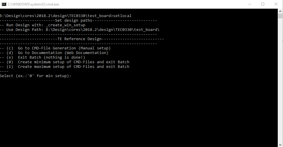
Run _create_win_setup.cmd/_create_linux_setup.sh and follow instructions on shell:
Code Block language bash theme Midnight title _create_win_setup.cmd/_create_linux_setup.sh ------------------------Set design paths---------------------------- -- Run Design with: _create_win_setup -- Use Design Path: <absolute project path> -------------------------------------------------------------------- -------------------------TE Reference Design--------------------------- -------------------------------------------------------------------- -- (0) Module selection guide, project creation...prebuilt export... -- (1) Create minimum setup of CMD-Files and exit Batch -- (2) Create maximum setup of CMD-Files and exit Batch -- (3) (internal only) Dev -- (4) (internal only) Prod -- (c) Go to CMD-File Generation (Manual setup) -- (d) Go to Documentation (Web Documentation) -- (g) Install Board Files from Xilinx Board Store (beta) -- (a) Start design with unsupported Vivado Version (beta) -- (x) Exit Batch (nothing is done!) ---- Select (ex.:'0' for module selection guide):Press 0 and enter to start "Module Selection Guide"
- (optional Win OS) Generate Virtual Drive or use short directory for the reference design (for example x:\<design name>)
- Createproject and follow instructions of the product selection guide, settings file will be configured automatically during this process.
optional for manual changes: Select correct device and Xilinx install path on "design_basic_settings.cmd" and create Vivado project with "vivado_create_project_guimode.cmd"
Note Note: Select correct one, see also Vivado Board Part Flow
Create hardware description file (.xsa file) for PetaLinux project and export to prebuilt folder
Code Block language py theme Midnight title run on Vivado TCL (Script generates design and export files into "<project folder>\prebuilt\hardware\<short name>") TE::hw_build_design -export_prebuiltInfo Using Vivado GUI is the same, except file export to prebuilt folder.
Generate Programming Files with Vitis
Code Block language py theme Midnight title run on Vivado TCL (Script generates applications and bootable files, which are defined in "test_board\sw_lib\apps_list.csv") TE::sw_run_vitis -all TE::sw_run_vitis (optional; Start Vitis from Vivado GUI or start with TE Scripts on Vivado TCL)Note TCL scripts generate also platform project, this must be done manually in case GUI is used. See Vitis
(Optional) BlockRam Firmware Update
Copy "<project folder>\prebuilt\software\<short name>\spi_bootloader.elf" into "<project folder>\firmware\microblaze_0\"
Copy "<project folder>\workspace\sdk\scu\Release\scu.elf" into "\firmware\microblaze_mcs_0\"
Regenerate Vivado Project or Update Bitfile only with "spi_bootloader.elf" and "scu_te0712.elf"
Code Block language bash theme Midnight TE::hw_build_design -export_prebuilt TE::sw_run_vitis -all
Launch
| Scroll Ignore | ||||||||||||||
|---|---|---|---|---|---|---|---|---|---|---|---|---|---|---|
| ||||||||||||||
Programming
| Page properties | ||||
|---|---|---|---|---|
| ||||
Note:
|
| Note |
|---|
Check Module and Carrier TRMs for proper HW configuration before you try any design. Reference Design is also available with prebuilt files. It's recommended to use TE prebuilt files for first launch. |
Xilinx documentation for programming and debugging: Vivado/Vitis/SDSoC-Xilinx Software Programming and Debugging
Get prebuilt boot binaries
- Run _create_win_setup.cmd/_create_linux_setup.sh and follow instructions on shell
- Press 0 and enter to start "Module Selection Guide"
- Select assembly version
- Validate selection
Select create and open delivery binary folder
Info Note: Folder "<project folder>\_binaries_<Article Name>" with subfolder "boot_<app name>" for different applications will be generate
QSPI-Boot mode
- Connect JTAG and Power ON PC
- Open Vivado Project with "vivado_open_existing_project_guimode.cmd" or if not created, create with "vivado_create_project_guimode.cmd"
Type on Vivado TCL Console:
Code Block language py theme Midnight title run on Vivado TCL (Script programs u-boot.mcs onto QSPI flash) TE::pr_program_flash -swapp hello_tec0330- Reboot PC
SD-Boot mode
Not used on this Example.
JTAG
- Connect Vivado HW Manager and program FPGA
Usage
- Prepare HW like described on section Programming
- Power On PCB
Note: 1. FPGA Load Bitfile into FPGA,MCS configure SI5338 and starts microblaze design, modified SPI Bootloader to load hello_tec0330 application from QSPI into DDR (Depends on linker script)
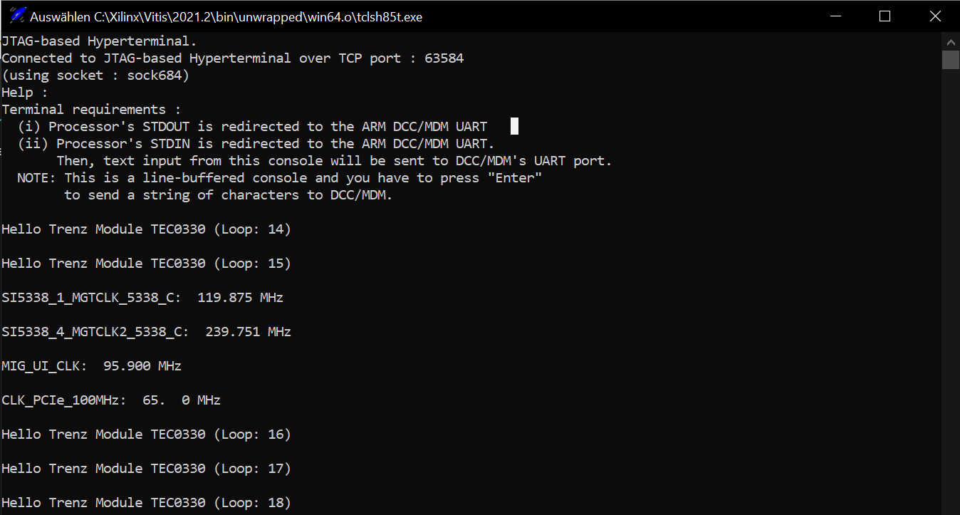
JTAG/UART Console:
- Launch XSCT or the XSDB console on Vitis:
- type: connect
- type: targets -set -filter {name =~ "MicroBlaze Debug*"} -index 0
- type: jtagterminal -start
- Separate console starts printing out four internal frequencies(can also be seen in the hardware manager) and "Hello Trenz Module" in a loop:
Vivado HW Manager:
| Page properties | ||||
|---|---|---|---|---|
| ||||
Note:
|
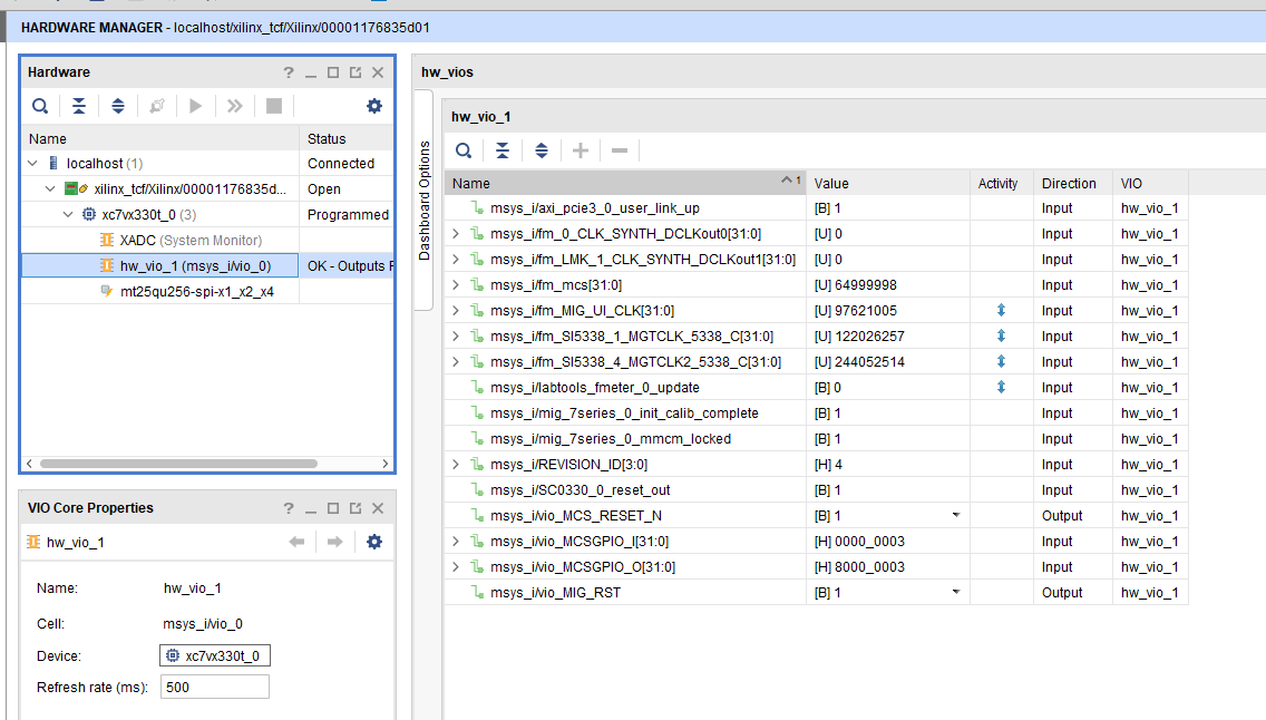
- Open Vivado HW Manager
- Add VIO to Dashboard
- Set Radix to unsigned integer for FMeterCLKs (fm_*). Note measurement is not accurate
- Control:
- MCS Reset
- MIG Reset
- Read: SI5338 CLKs (Unit Hz), PCIe Core User Link Up signal, MIG MMCM Lock signal, MIG Init Calibration Done signal, PCB Revision ID
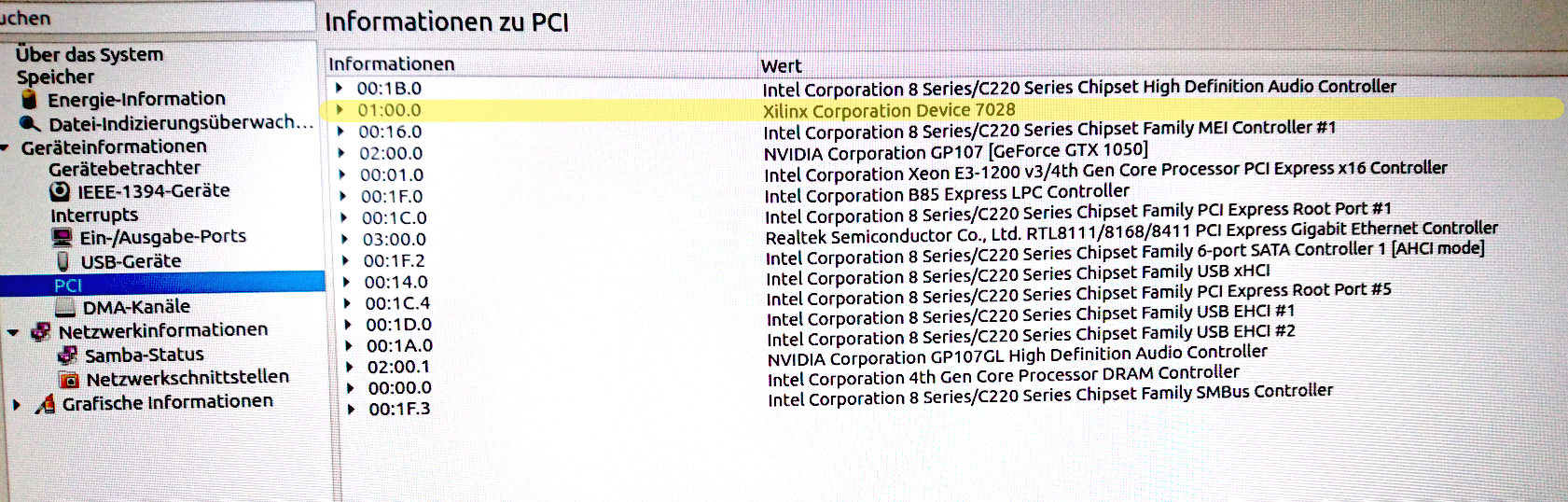
PC:
- Use for example PCI-Z (Win) or KInfoCenter (Linux) to detect PCIe Card
System Design - Vivado
| Scroll Ignore | ||||||||||||||
|---|---|---|---|---|---|---|---|---|---|---|---|---|---|---|
| ||||||||||||||
| Page properties | ||||
|---|---|---|---|---|
| ||||
Note:
|
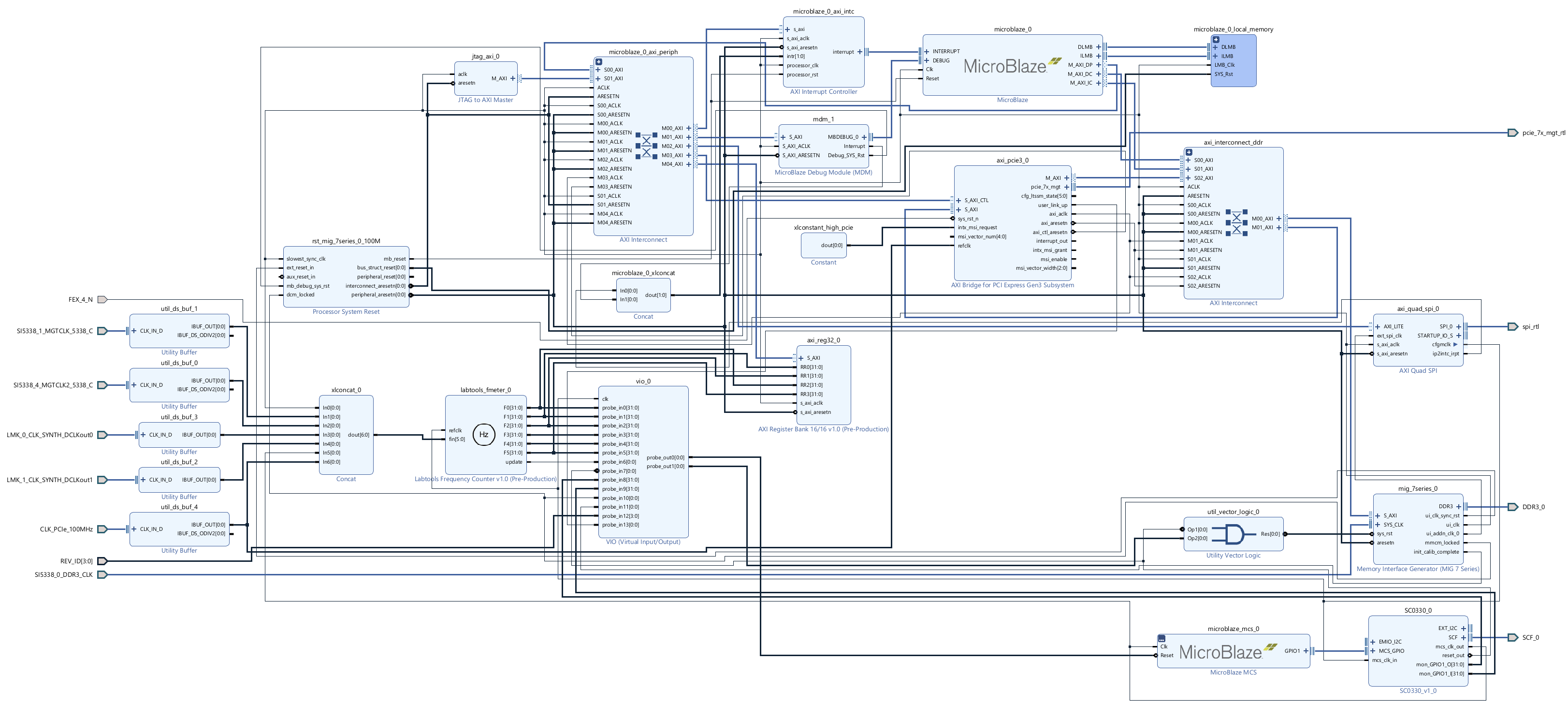
Block Design
| Scroll Title | ||||||
|---|---|---|---|---|---|---|
| ||||||
|
Constraints
Basic module constrains
| Code Block | ||||
|---|---|---|---|---|
| ||||
#
# Default common settings that do not depend assembly variant
#
set_property BITSTREAM.GENERAL.COMPRESS TRUE [current_design]
set_property BITSTREAM.CONFIG.CONFIGRATE 66 [current_design]

set_property BITSTREAM.CONFIG.SPI_32BIT_ADDR YES [current_design]
set_property BITSTREAM.CONFIG.SPI_BUSWIDTH 4 [current_design]
set_property BITSTREAM.CONFIG.M1PIN PULLNONE [current_design]
set_property BITSTREAM.CONFIG.M2PIN PULLNONE [current_design]
set_property BITSTREAM.CONFIG.M0PIN PULLNONE [current_design]

set_property BITSTREAM.CONFIG.USR_ACCESS TIMESTAMP [current_design] |
| Code Block | ||||
|---|---|---|---|---|
| ||||
#
#
#
set_property BITSTREAM.CONFIG.UNUSEDPIN PULLDOWN [current_design] |
Design specific constrain
| Code Block | ||||
|---|---|---|---|---|
| ||||
#----------
#IIC to CPLD
set_property PACKAGE_PIN W29 [get_ports SCF_0_cpld_25_scl]
set_property PACKAGE_PIN W26 [get_ports SCF_0_cpld_19_oe]
set_property PACKAGE_PIN V29 [get_ports SCF_0_cpld_24_sda]
set_property IOSTANDARD LVCMOS18 [get_ports SCF_0_cpld_25_scl]
set_property IOSTANDARD LVCMOS18 [get_ports SCF_0_cpld_19_oe]
set_property IOSTANDARD LVCMOS18 [get_ports SCF_0_cpld_24_sda]
#----------
#PCIe
set_property PACKAGE_PIN E33 [get_ports FEX_4_N]
set_property IOSTANDARD LVCMOS18 [get_ports FEX_4_N]
set_property PACKAGE_PIN AD6 [get_ports {CLK_PCIe_100MHz_clk_p[0]}]
#todo check auto placement:
set_property CLOCK_DEDICATED_ROUTE FALSE [get_nets msys_i/axi_pcie3_0/inst/pcie3_ip_i/inst/gt_top_i/pipe_wrapper_i/pipe_lane[0].gt_wrapper_i/CLK_TXOUTCLK]
#----------
#Revision ID
set_property PACKAGE_PIN AP27 [get_ports {REV_ID[0]}]
set_property PACKAGE_PIN AN27 [get_ports {REV_ID[1]}]
set_property PACKAGE_PIN AP26 [get_ports {REV_ID[2]}]
set_property PACKAGE_PIN AP25 [get_ports {REV_ID[3]}]
set_property IOSTANDARD LVCMOS18 [get_ports {REV_ID[*]}]
#----------
#QSPI
set_property PACKAGE_PIN AL33 [get_ports {spi_rtl_ss_io[0]}]
set_property IOSTANDARD LVCMOS18 [get_ports {spi_rtl_ss_io[0]}]
set_property PACKAGE_PIN AN33 [get_ports spi_rtl_io0_io]
set_property PACKAGE_PIN AN34 [get_ports spi_rtl_io1_io]
set_property PACKAGE_PIN AK34 [get_ports spi_rtl_io2_io]
set_property PACKAGE_PIN AL34 [get_ports spi_rtl_io3_io]
set_property IOSTANDARD LVCMOS18 [get_ports spi_rtl_io0_io]
set_property IOSTANDARD LVCMOS18 [get_ports spi_rtl_io1_io]
set_property IOSTANDARD LVCMOS18 [get_ports spi_rtl_io2_io]
set_property IOSTANDARD LVCMOS18 [get_ports spi_rtl_io3_io]
#----------
#CLKS
##SI5338_0_DDR3_CLK #diff 1.5V AG17/AH17
set_property PACKAGE_PIN AG17 [get_ports {SI5338_0_DDR3_CLK_clk_p}]
set_property IOSTANDARD DIFF_SSTL15 [get_ports {SI5338_0_DDR3_CLK_clk_p}]
##SI5338_1_MGTCLK_5338_C #diff MGT 1.8V AB6/AB5
set_property PACKAGE_PIN AB6 [get_ports {SI5338_1_MGTCLK_5338_C_clk_p[0]}]
###SI5338_3_LMK_CLK #diff MGT 1.8V to LMK CLKin1
##SI5338_4_MGTCLK2_5338_C #diff MGT 1.8V H6/H5
set_property PACKAGE_PIN H6 [get_ports {SI5338_4_MGTCLK2_5338_C_clk_p[0]}]
##LMK_0_CLK_SYNTH_DCLKout0 #diff  1.8V AD29/AE29
set_property PACKAGE_PIN AD29 [get_ports {LMK_0_CLK_SYNTH_DCLKout0_clk_p[0]}]
set_property IOSTANDARD LVDS [get_ports {LMK_0_CLK_SYNTH_DCLKout0_clk_p[0]}]
set_property DIFF_TERM TRUE [get_ports {LMK_0_CLK_SYNTH_DCLKout0_clk_p[0]}]
##LMK_1_CLK_SYNTH_DCLKout1 #diff  1.8V AE31/AF31
set_property PACKAGE_PIN AE31 [get_ports {LMK_1_CLK_SYNTH_DCLKout1_clk_p[0]}]
set_property IOSTANDARD LVDS [get_ports {LMK_1_CLK_SYNTH_DCLKout1_clk_p[0]}]
set_property DIFF_TERM TRUE [get_ports {LMK_1_CLK_SYNTH_DCLKout1_clk_p[0]}]
###LMK_2_CLKIN_5338_P #diff  1.8Vto Si5338 IN1/IN2
###LMK_3_CLK_SYNTH_SDCLKout3 #diff  1.8Vto N.C.
###LMK_4_CLK_SYNTH_SDCLKout4 #diff MGT 1.8V T6/T5
###LMK_5_CLK_SYNTH_SDCLKout5 #diff  1.8Vto N.C.
###LMK_6_CLK_SYNTH_SDCLKout6 #diff  1.8Vto N.C.
###LMK_7_CLK_SYNTH_SDCLKout7 #diff MGT 1.8V F6/F5
###LMK_8_CLK_SYNTH_SDCLKout8 #diff  1.8Vto N.C.
###LMK_9_CLK_SYNTH_SDCLKout9 #diff  1.8Vto N.C.
###LMK_10_CLK_SYNTH_SDCLKout10 #diff  1.8Vto N.C.
###LMK_11_CLK_SYNTH_SDCLKout11 #diff  1.8Vto N.C.
###LMK_12_CLK_SYNTH_SDCLKout12 #diff  1.8Vto N.C.
###LMK_13_CLK_SYNTH_SDCLKout13 #diff  1.8Vto N.C.


#----------
|
Software Design - Vitis
| Scroll Ignore | ||||||||||||||
|---|---|---|---|---|---|---|---|---|---|---|---|---|---|---|
| ||||||||||||||
| Page properties | ||||
|---|---|---|---|---|
| ||||
Note:
|
For Vitis project creation, follow instructions from:
Application
| Page properties | ||||
|---|---|---|---|---|
| ||||
---------------------------------------------------------- FPGA Example scuMCS Firmware to configure SI5338 and Reset System. spi_bootloaderTE modified SPI Bootloader from Henrik Brix Andersen. Bootloader to load app or second bootloader from flash into DDR Descriptions:
xilisf_v5_11TE modified 2020.2 xilisf_v5_11
---------------------------------------------------------- Zynq Example: fsblTE modified 2020.2 FSBL General:
Module Specific:
fsbl_flashTE modified 2020.2 FSBL General:
ZynqMP Example: ---------------------------------------------------------- zynqmp_fsblTE modified 2020.2 FSBL General:
Module Specific:
zynqmp_fsbl_flashTE modified 2020.2 FSBL General:
zynqmp_pmufwXilinx default PMU firmware. ---------------------------------------------------------- General Example: hello_te0820Hello TE0820 is a Xilinx Hello World example as endless loop instead of one console output. u-bootU-Boot.elf is generated with PetaLinux. Vitis is used to generate Boot.bin. eepromeeprom is a petalinux application that executes on startup. It reads the unique 48-bit MAC from the onboard eeprom and uses it to set the system MAC address. |
...
...
scu
- Si5338 I2C Configuration via MCS.
srec_spi_bootloader
...
...
modified Files: blconfig.h, bootloader.c
...
...
...
Overview
Content Tools