Page History
...
| HTML |
|---|
<!-- General Design description --> |
Zynq PS Design with Linux Example. Add simple frequency counter to measure SI5338 Reference CLK and RGPIO IP to get access to CPLD IOs with Vivado HW-Manager.
Key Features
| HTML |
|---|
<!-- Add Basic Key Features of the design (should be tested) --> |
| Excerpt |
|---|
|
...
| HTML |
|---|
<!-- - Add changes from design - Export PDF to download, if vivado revision is changed! --> |
| Date | Vivado | Project Built | Authors | Description |
|---|---|---|---|---|
| 2018-06-01 | 2017.4 |
Release Notes and Know Issues
| TE0783-test_board_noprebuilt-vivado_2017.4-build_10_20180611114036.zip TE0783-test_board-vivado_2017.4-build_10_20180611114017.zip | John Hartfiel | initial release |
Release Notes and Know Issues
| HTML |
|---|
<!--
- add |
| HTML |
<!--
- add known Design issues and general Notes for the current revision
--> |
...
For general structure and of the reference design, see Project Delivery - AMD devices
Design Sources
| Type | Location | Notes |
|---|---|---|
| Vivado | <design name>/block_design <design name>/constraints <design name>/ip_lib | Vivado Project will be generated by TE Scripts |
| SDK/HSI | <design name>/sw_lib | Additional Software Template for SDK/HSI and apps_list.csv with settings for HSI |
| PetaLinux | <design name>/os/petalinux | PetaLinux template with current configuration |
...
Trenz Electronic provides a tcl based built environment based on Xilinx Design Flow.
See also:
- Vivado/SDK/SDSoCAMD Development Tools#XilinxSoftware-BasicUserGuides
- Vivado Projects - TE Reference Design
- Project Delivery.
The Trenz Electronic FPGA Reference Designs are TCL-script based project. Command files for execution will be generated with "_create_win_setup.cmd" on Windows OS and "_create_linux_setup.sh" on Linux OS.
TE Scripts are only needed to generate the vivado project, all other additional steps are optional and can also executed by Xilinx Vivado/SDK GUI. For currently Scripts limitations on Win and Linux OS see: Project Delivery Currently limitations of functionality
- _create_win_setup.cmd/_create_linux_setup.sh and follow instructions on shell:
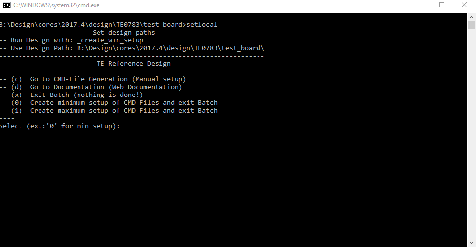
- Press 0 and enter for minimum setup
- (optional Win OS) Generate Virtual Drive or use short directory for the reference design (for example x:\<design name>)
- Create Project
- Select correct device and Xilinx install path on "design_basic_settings.cmd" and create Vivado project with "vivado_create_project_guimode.cmd"
Note: Select correct one, see TE Board Part Files
- Select correct device and Xilinx install path on "design_basic_settings.cmd" and create Vivado project with "vivado_create_project_guimode.cmd"
- Create HDF and export to prebuilt folder
- Run on Vivado TCL: TE::hw_build_design -export_prebuilt
Note: Script generate design and export files into \prebuilt\hardware\<short dir>. Use GUI is the same, except file export to prebuilt folder
- Run on Vivado TCL: TE::hw_build_design -export_prebuilt
- Create Linux (uboot.elf and image.ub) with exported HDF
- HDF is exported to "prebuilt\hardware\<short name>"
Note: HW Export from Vivado GUI create another path as default workspace. - Create Linux images on VM, see PetaLinux KICKstart
- Use TE Template from /os/petalinux
Note: run init_config.sh before you start petalinux config. This will set correct temporary path variable.
- Use TE Template from /os/petalinux
- HDF is exported to "prebuilt\hardware\<short name>"
- Add Linux files (uboot.elf and image.ub) to prebuilt folder
- "prebuilt\os\petalinux\default" or "prebuilt\os\petalinux\<short name>"
Notes: Scripts select "prebuilt\os\petalinux\<short name>", if exist, otherwise "prebuilt\os\petalinux\default"
- "prebuilt\os\petalinux\default" or "prebuilt\os\petalinux\<short name>"
- Generate Programming Files with HSI/SDK
- Run on Vivado TCL: TE::sw_run_hsi
Note: Scripts generate applications and bootable files, which are defined in "sw_lib\apps_list.csv" - (alternative) Start SDK with Vivado GUI or start with TE Scripts on Vivado TCL: TE::sw_run_sdk
Note: See SDK Projects
- Run on Vivado TCL: TE::sw_run_hsi
...
Xilinx documentation for programming and debugging: Vivado/SDK/SDSoC-Xilinx Software Programming and Debugging
QSPI
Optional for Boot.bin on QSPI Flash and image.ub on SD.
- Connect JTAG and power on carrier with module
- Open Vivado Project with "vivado_open_existing_project_guimode.cmd" or if not created, create with "vivado_create_project_guimode.cmd"
- Type on Vivado TCL Console: TE::pr_program_flash_binfile -swapp u-boot
Note: To program with SDK/Vivado GUI, use special FSBL (zynqmp_fsbl_flash) on setupCopy image.ub on
SD
...
- For correct prebuilt file location, see <design_name>/prebuilt/readme_file_location.txt
...
Not used
SD
Not used on this Example.
JTAG
Not used on this Example.
...
- Open Serial Console (e.g. putty)
- Speed: 115200
- COM Port: Win OS, see device manager, Linux OS see dmesg |grep tty (UART is *USB1)
- Linux Console:
Note: Wait until Linux boot finished For Linux Login use:- User Name: root
- Password: root
- You can use Linux shell now.
- I2C 0 Bus type: i2cdetect -y -r 0
- RTC check: dmesg | grep rtc
- ETH0 works with udhcpc
- USB type "lsusb" or connect USB2.0 device
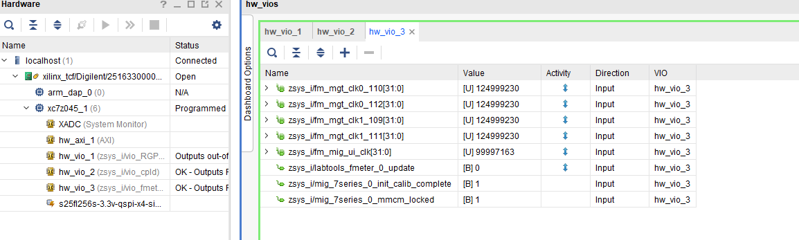
Vivado HW Manager
SI5338 MGT Reference CLKs:
- Open Vivado HW-Manager and add VIO signal to dashboard (*.ltx located on prebuilt folder).
- Set radix from VIO signals to unsigned integer.
Note: Frequency Counter is inaccurate and displayed unit is Hz - SI5338 CLK is CLKs are configured to to 125MHz with example FSBL initialisation.
Status Signals
PL MIG Status Status signal:
- Status signals connected to VIO
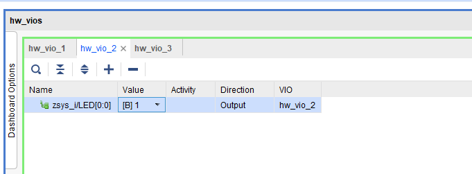
Custom LED
Red LED D1 can be controlled via VIO.
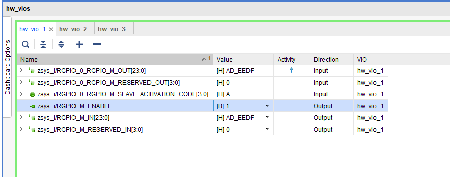
RGPIO
RGPIO Pins can be controlled via VIO
 TODO Bild
System Design - Vivado
| HTML |
|---|
<!-- Description of Block Design, Constrains... BD Pictures from Export... --> |
Block Design
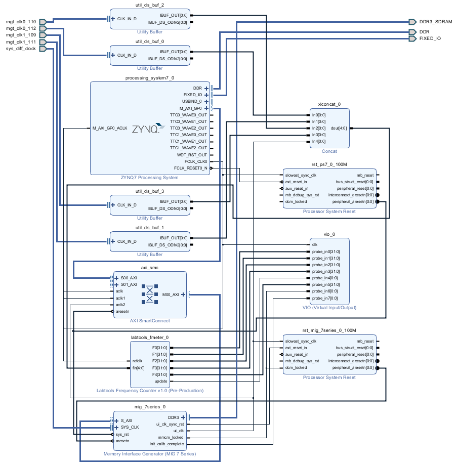
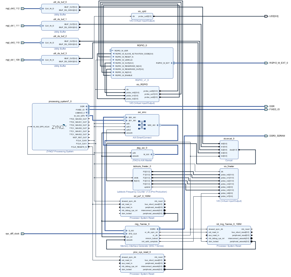
PS Interfaces
| Typ | Note |
|---|---|
| DDR3 | |
| QSPI | MIO |
| ETH0 | MIO |
| USB0 | MIO |
| SD0 | MIO |
| SD1 | MIO |
| I2C0 | MIO |
| SWDT0..1 | |
| TTC0..3 |
Constrains
Basic module constrains
...
Design specific constrain
| Code Block | ||||
|---|---|---|---|---|
| ||||
#set_property PACKAGE_PIN AA8 [get_ports {SI_MGT_CLK0_110_clk_p[0]}]
#set_property PACKAGE_PIN N8 [get_ports {SI_MGT_CLK0_112_clk_p[0]}]
#set_property PACKAGE_PIN AF10 [get_ports {SI_MGT_CLK1_109_clk_p[0]}]
#set_property PACKAGE_PIN W8 [get_ports {SI_MGT_CLK1_111_clk_p[0]}]
#set_property IOSTANDARD DIFF_SSTL15 [get_ports {MIG_SYS_CLK_clk_p[0]}]
#set_property PACKAGE_PIN H9 [get_ports {MIG_SYS_CLK_clk_p[0]}]
# -------------
#LED
set_property PACKAGE_PIN AE20 [get_ports {LED[0]}]
set_property IOSTANDARD LVCMOS33 [get_ports {LED[0]}]
# -------------
#RGPIO
set_property PACKAGE_PIN AB19 [get_ports RGPIO_M_EXT_0_clk]
set_property PACKAGE_PIN AB20 [get_ports RGPIO_M_EXT_0_rx]
set_property PACKAGE_PIN AD20 [get_ports RGPIO_M_EXT_0_tx]
set_property IOSTANDARD LVCMOS33 [get_ports RGPIO_M_EXT_0_clk]
set_property IOSTANDARD LVCMOS33 [get_ports RGPIO_M_EXT_0_rx]
set_property IOSTANDARD LVCMOS33 [get_ports RGPIO_M_EXT_0_tx] |
| Code Block | ||||
|---|---|---|---|---|
| ||||
set_false_path -from [get_clocks clk_fpga_0] -to [get_clocks {zsys_i/util_ds_buf_0/U0/IBUF_OUT[0]}]
set_false_path -from [get_clocks clk_fpga_0] -to [get_clocks {zsys_i/util_ds_buf_1/U0/IBUF_OUT[0]}]
set_false_path -from [get_clocks clk_fpga_0] -to [get_clocks {zsys_i/util_ds_buf_2/U0/IBUF_OUT[0]}]
set_false_path -from [get_clocks clk_fpga_0] -to [get_clocks {zsys_i/util_ds_buf_3/U0/IBUF_OUT[0]}]
set_false_path -from [get_clocks {zsys_i/util_ds_buf_0/U0/IBUF_OUT[0]}] -to [get_clocks clk_fpga_0]
set_false_path -from [get_clocks {zsys_i/util_ds_buf_1/U0/IBUF_OUT[0]}] -to [get_clocks clk_fpga_0]
set_false_path -from [get_clocks {zsys_i/util_ds_buf_2/U0/IBUF_OUT[0]}] -to [get_clocks clk_fpga_0]
set_false_path -from [get_clocks {zsys_i/util_ds_buf_3/U0/IBUF_OUT[0]}] -to [get_clocks clk_fpga_0] | ||||
| Code Block | ||||
| language | ruby | title | _i_io.xdc
Software Design - SDK/HSI
...
Source location: \sw_lib\sw_apps
...
zynq_fsbl
TE modified 207.4 FSBL
Changes:
- SI5338 initialisation
...
- Si5338 Configuration
- see main.c, fsbl_hooks.c
- Add register_map.h, si5338.c, si5338.h
zynq_fsbl_flash
TE modified 2017.4 FSBL
Changes:
...
| Date | Document Revision | Authors | Description | ||||||||||||||||||||||||
|---|---|---|---|---|---|---|---|---|---|---|---|---|---|---|---|---|---|---|---|---|---|---|---|---|---|---|---|
|
|
|
| ||||||||||||||||||||||||
| v.4 | John Hartfiel | Release 2017.4 | |||||||||||||||||||||||||
| 2018-05-30 | v.1 |
|
| ||||||||||||||||||||||||
| All |
|
...
Overview
Content Tools