Page History
...
| Page properties | ||||
|---|---|---|---|---|
| ||||
Template Revision 2.2 8 - on construction Design Name always "TE Series Name" + Design name, for example "TE0720 Test Board" |
...
| Page properties | ||||
|---|---|---|---|---|
| ||||
Notes :
|
| Excerpt |
|---|
|
...
| Scroll Title | |||||||||||||||||||||||||||||||||||||||||
|---|---|---|---|---|---|---|---|---|---|---|---|---|---|---|---|---|---|---|---|---|---|---|---|---|---|---|---|---|---|---|---|---|---|---|---|---|---|---|---|---|---|
| |||||||||||||||||||||||||||||||||||||||||
|
Release Notes and Know Issues
| Page properties | ||||
|---|---|---|---|---|
| ||||
Notes :
|
...
| anchor | Table_KI |
|---|---|
| title | Known Issues |
|
Release Notes and Know Issues
...
Requirements
...
| Page properties | ||||
|---|---|---|---|---|
| ||||
Notes :
|
| Scroll Title | ||||||||||||||||||||||||||||||||||||
|---|---|---|---|---|---|---|---|---|---|---|---|---|---|---|---|---|---|---|---|---|---|---|---|---|---|---|---|---|---|---|---|---|---|---|---|---|
| ||||||||||||||||||||||||||||||||||||
Software
Note | Vivado | 2018.2 | needed | SDK | 2018.2 | needed | PetaLinux | 2018.2 | needed | SI5338 Clock Builder | --- | optional | SI5345 Clock Builder Pro | --- | optional | |
Hardware
|
Requirements
Software
| Page properties | ||||
|---|---|---|---|---|
| ||||
Notes :
|
Basic description of TE Board Part Files is available on TE Board Part Files.
...
Design supports following modules:
| Scroll Title | ||||||||||||||||||
|---|---|---|---|---|---|---|---|---|---|---|---|---|---|---|---|---|---|---|
| ||||||||||||||||||
| ||||||||||||||||||
| Module Model | Board Part Short Name | PCB Revision Support | DDR | QSPI Flash | Others | Notes | REV02, REV01 | SODIMM, configured for 4GB: KVR24S17S8/8 | 64MB |
| TEB0911-04-09EG-1E | 9eg_1e | REV04, REV03, REV02 | SODIMM, configured for 8GB: CT8G4SFS824A | 64MB | TEB0911-04-15EG-1E | 15eg_1e | REV04 | SODIMM, configured for 8GB: CT8G4SFS824A | 64MB |
| Software | Version | Note |
|---|---|---|
| Vitis | 2019.2 | needed, Vivado is included into Vitis installation |
| PetaLinux | 2019.2 | needed |
| SI ClockBuilder Pro | --- | optional |
Hardware
| Page properties | ||||
|---|---|---|---|---|
| ||||
Notes :
|
Basic description of TE Board Part Files is available on TE Board Part Files.
Complete List is available on <design name>/board_files/*_board_files.csv
Design supports following modulesAdditional HW Requirements:
| Scroll Title | ||||||||||||||||||
|---|---|---|---|---|---|---|---|---|---|---|---|---|---|---|---|---|---|---|
| ||||||||||||||||||
| ||||||||||||||||||
| Additional Hardware | Notes | |||||||||||||||||
| DDR4 | example configured for CT8G4SFS824A |
Content
| Page properties | ||||
|---|---|---|---|---|
| ||||
Notes :
|
For general structure and of the reference design, see Project Delivery - Xilinx devices
Design Sources
...
| anchor | Table_DS |
|---|---|
| title | Design sources |
...
|
Additional HW Requirements:
...
| Scroll Title | ||||||||||||||||||||||||||||||
|---|---|---|---|---|---|---|---|---|---|---|---|---|---|---|---|---|---|---|---|---|---|---|---|---|---|---|---|---|---|---|
| ||||||||||||||||||||||||||||||
|
...
|
Content
| Page properties | ||||
|---|---|---|---|---|
| ||||
Notes :
|
For general structure and of the reference design, see Project Delivery - AMD devices
Design Sources
| Scroll Title | ||||||||||||||||||||||||||||||
|---|---|---|---|---|---|---|---|---|---|---|---|---|---|---|---|---|---|---|---|---|---|---|---|---|---|---|---|---|---|---|
| PF
| Prebuilt files
| ||||||||||||||||||||||||||||
|
Additional Sources
| Scroll Title | ||||||||||||||||||||||||||||||
|---|---|---|---|---|---|---|---|---|---|---|---|---|---|---|---|---|---|---|---|---|---|---|---|---|---|---|---|---|---|---|
| ||||||||||||||||||||||||||||||
|
Prebuilt
| Page properties | |||||||||||||||||||||||||||||||||||||||||||||||||||||||||||||||||||||||||||||||||||||||||||||||||||||||||||||||
|---|---|---|---|---|---|---|---|---|---|---|---|---|---|---|---|---|---|---|---|---|---|---|---|---|---|---|---|---|---|---|---|---|---|---|---|---|---|---|---|---|---|---|---|---|---|---|---|---|---|---|---|---|---|---|---|---|---|---|---|---|---|---|---|---|---|---|---|---|---|---|---|---|---|---|---|---|---|---|---|---|---|---|---|---|---|---|---|---|---|---|---|---|---|---|---|---|---|---|---|---|---|---|---|---|---|---|---|---|---|---|---|
| |||||||||||||||||||||||||||||||||||||||||||||||||||||||||||||||||||||||||||||||||||||||||||||||||||||||||||||||
Notes :
| (only on ZIP with prebult content)
| Diverse Reports | ---
|
xsa Exported Vivado Hardware Specification for
Vitis and PetaLinux LabTools Project-File *.lpr Vivado Labtools Project File MCS-File
*.mcs
Flash Configuration File with Boot-Image (MicroBlaze or FPGA part only)
MMI-File
*.mmi
File with BRAM-Location to generate MCS or BIT-File with *.elf content (MicroBlaze only)
OS-Image *.ub Image with Linux Kernel (On Petalinux optional with Devicetree and RAM-Disk) Software-Application-File *.elf Software Application for Zynq or MicroBlaze Processor Systems
Download
Reference Design is only usable with the specified Vivado/SDK/PetaLinux/SDx version. Do never use different Versions of Xilinx Software for the same Project.
| Page properties | ||||
|---|---|---|---|---|
| ||||
|
Reference Design is available on:
Design Flow
| Page properties | ||||
|---|---|---|---|---|
| ||||
Notes :
|
| Note |
|---|
Reference Design is available with and without prebuilt files. It's recommended to use TE prebuilt files for first lunch. |
Trenz Electronic provides a tcl based built environment based on Xilinx Design Flow.
See also:
The Trenz Electronic FPGA Reference Designs are TCL-script based project. Command files for execution will be generated with "_create_win_setup.cmd" on Windows OS and "_create_linux_setup.sh" on Linux OS.
TE Scripts are only needed to generate the vivado project, all other additional steps are optional and can also executed by Xilinx Vivado/SDK GUI. For currently Scripts limitations on Win and Linux OS see: Project Delivery Currently limitations of functionality
- _create_win_setup.cmd/_create_linux_setup.sh and follow instructions on shell:
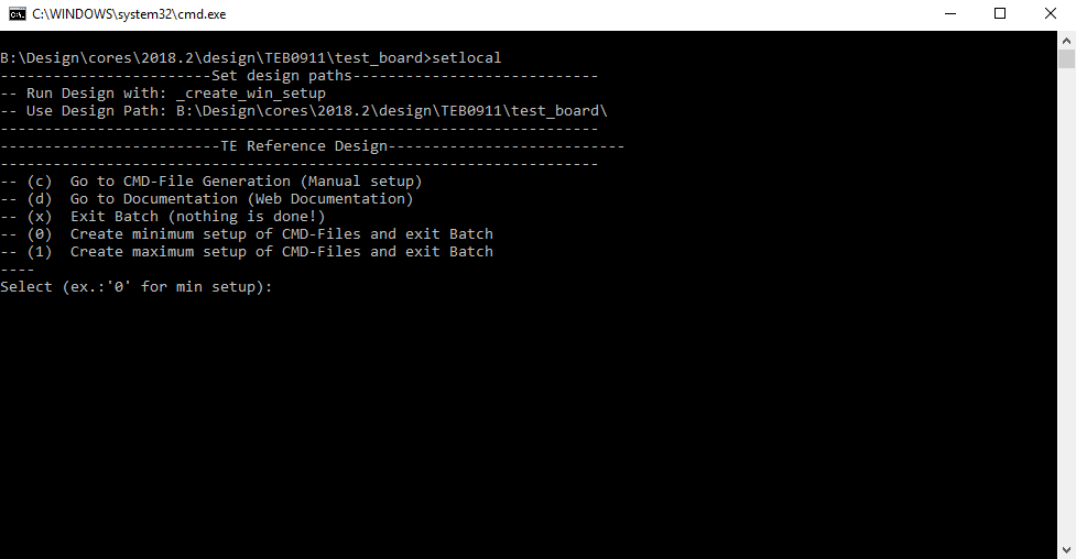
- Press 0 and enter for minimum setup
- (optional Win OS) Generate Virtual Drive or use short directory for the reference design (for example x:\<design name>)
- Create Project
- Select correct device and Xilinx install path on "design_basic_settings.cmd" and create Vivado project with "vivado_create_project_guimode.cmd"
Note: Select correct one, see TE Board Part Files
- Select correct device and Xilinx install path on "design_basic_settings.cmd" and create Vivado project with "vivado_create_project_guimode.cmd"
- Create HDF and export to prebuilt folder
- Run on Vivado TCL: TE::hw_build_design -export_prebuilt
Note: Script generate design and export files into \prebuilt\hardware\<short dir>. Use GUI is the same, except file export to prebuilt folder
- Run on Vivado TCL: TE::hw_build_design -export_prebuilt
- Create Linux (uboot.elf and image.ub) with exported HDF
- HDF is exported to "prebuilt\hardware\<short name>"
Note: HW Export from Vivado GUI create another path as default workspace. - Create Linux images on VM, see PetaLinux KICKstart
- Use TE Template from /os/petalinux
- HDF is exported to "prebuilt\hardware\<short name>"
- Add Linux files (uboot.elf and image.ub) to prebuilt folder
- "prebuilt\os\petalinux\default" or "prebuilt\os\petalinux\<short name>"
Notes: Scripts select "prebuilt\os\petalinux\<short name>", if exist, otherwise "prebuilt\os\petalinux\default"
- "prebuilt\os\petalinux\default" or "prebuilt\os\petalinux\<short name>"
- Generate Programming Files with HSI/SDK
- Run on Vivado TCL: TE::sw_run_hsi
Note: Scripts generate applications and bootable files, which are defined in "sw_lib\apps_list.csv" - (alternative) Start SDK with Vivado GUI or start with TE Scripts on Vivado TCL: TE::sw_run_sdk
Note: See SDK Projects
- Run on Vivado TCL: TE::sw_run_hsi
Launch
| Page properties | ||||
|---|---|---|---|---|
| ||||
Note:
|
Programming
| Note |
|---|
Check Module and Carrier TRMs for proper HW configuration before you try any design. |
Xilinx documentation for programming and debugging: Vivado/SDK/SDSoC-Xilinx Software Programming and Debugging
QSPI
Optional for Boot.bin on QSPI Flash and image.ub on SD.
- Connect JTAG and power on carrier with module
- Open Vivado Project with "vivado_open_existing_project_guimode.cmd" or if not created, create with "vivado_create_project_guimode.cmd"
- Type on Vivado TCL Console: TE::pr_program_flash_binfile -swapp u-boot
Note: To program with SDK/Vivado GUI, use special FSBL (zynqmp_fsbl_flash) on setup
Optional "TE::pr_program_flash_binfile -swapp hello_teb0911" possible - Copy image.ub and optional misc/sd/init.sh on SD-Card
- For correct prebuilt file location, see <design_name>/prebuilt/readme_file_location.txt
- Insert SD-Card
SD
- Copy image.ub, Boot.bin and misc/sd/init.sh on SD-Card.
- For correct prebuilt file location, see <design_name>/prebuilt/readme_file_location.txt
- Set Boot Mode to SD-Boot.
- Depends on CPLD Firmware, see SC0911 CPLD#BootMode
- Insert SD-Card in SD-Slot.
JTAG
Not used on this Example.
Usage
- Prepare HW like described on section 70156312
- Connect UART USB (same as FPGA JTAG)
- Select SD Card as Boot Mode (or QSPI - depending on step 1)
- (Optional) Insert PCIe Card (detection depends on Linux driver. Only some basic drivers are installed)
- (Optional) Connect DisplayPort Monitor (List of usable Monitors: https://www.xilinx.com/support/answers/68671.html)
- (Optional) Connect Network Cable
- Power On PCB
Note: 1. ZynqMP Boot ROM loads PMU Firmware and FSBL from SD into OCM, 2. FSBL loads ATF(bl31.elf) and U-boot from SD/QSPI into DDR, 3. U-boot load Linux from SD into DDR.
Linux
- Open Serial Console (e.g. putty)
- Speed: 115200
- COM Port: Win OS, see device manager, Linux OS see dmesg |grep tty (UART is *USB1)
- Linux Console:
Note: Wait until Linux boot finished For Linux Login use:- User Name: root
- Password: root
- You can use Linux shell now.
- I2C 0 Bus type: i2cdetect -y -r 0
- ETH0 works with udhcpc
- USB type "lsusb" or connect USB device
- PCIe type "lspci"
Vivado HW Manager
| Page properties | ||||
|---|---|---|---|---|
| ||||
Note:
|
Control:
- User LED Control (D16, D15)
Monitoring:
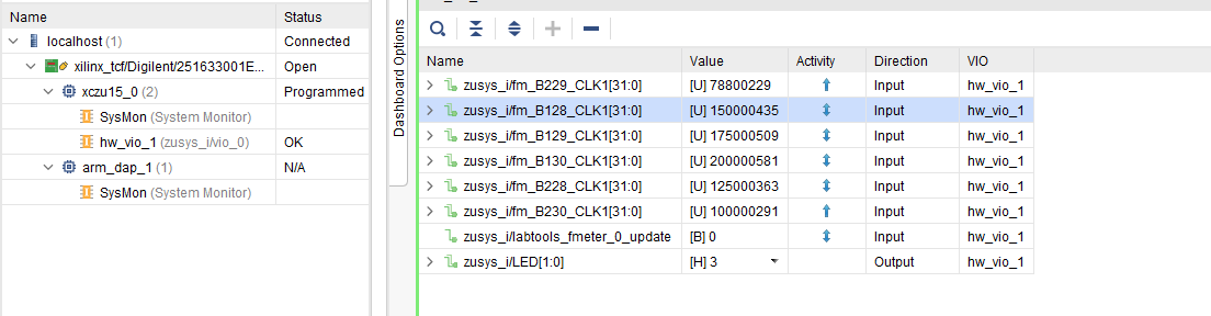
- MGT CLK Measurement:
- Open Vivado HW-Manager and add VIO signal to dashboard (*.ltx located on prebuilt folder).Set radix from VIO signals to unsigned integer.Note: Frequency Counter is inaccurate and displayed unit is Hz
- Default B229_CLK1: 78,8MHz, B128_CLK1: 150MHz, B129_CLK1: 175MHz, B130_CLK1: 200MHz, B228_CLK1: 125MHz, B23ß_CLK1: 100MHz
| Scroll Title | ||||
|---|---|---|---|---|
| ||||
 |
...
|
| Scroll Title | ||||||||||||||||||||||||||||||||||||||||||||||||
|---|---|---|---|---|---|---|---|---|---|---|---|---|---|---|---|---|---|---|---|---|---|---|---|---|---|---|---|---|---|---|---|---|---|---|---|---|---|---|---|---|---|---|---|---|---|---|---|---|
| ||||||||||||||||||||||||||||||||||||||||||||||||
|
Download
Reference Design is only usable with the specified Vivado/SDK/PetaLinux/SDx version. Do never use different Versions of Xilinx Software for the same Project.
| Page properties | ||||
|---|---|---|---|---|
| ||||
|
Reference Design is available on:
Design Flow
| Page properties | ||||
|---|---|---|---|---|
| ||||
Notes :
|
| Note |
|---|
Reference Design is available with and without prebuilt files. It's recommended to use TE prebuilt files for first lunch. |
Trenz Electronic provides a tcl based built environment based on Xilinx Design Flow.
See also:
- AMD Development Tools#XilinxSoftware-BasicUserGuides
- Vivado Projects - TE Reference Design
- Project Delivery.
The Trenz Electronic FPGA Reference Designs are TCL-script based project. Command files for execution will be generated with "_create_win_setup.cmd" on Windows OS and "_create_linux_setup.sh" on Linux OS.
TE Scripts are only needed to generate the vivado project, all other additional steps are optional and can also executed by Xilinx Vivado/SDK GUI. For currently Scripts limitations on Win and Linux OS see: Project Delivery Currently limitations of functionality
- _create_win_setup.cmd/_create_linux_setup.sh and follow instructions on shell:
- Press 0 and enter to start "Module Selection Guide"
- (optional Win OS) Generate Virtual Drive or use short directory for the reference design (for example x:\<design name>)
- Create Project (follow instruction of the product selection guide), settings file will be configured automatically during this process
- (optional for manual changes) Select correct device and Xilinx install path on "design_basic_settings.cmd" and create Vivado project with "vivado_create_project_guimode.cmd"
Note: Select correct one, see alsoTE Board Part Files
- (optional for manual changes) Select correct device and Xilinx install path on "design_basic_settings.cmd" and create Vivado project with "vivado_create_project_guimode.cmd"
- Create HDF and export to prebuilt folder
- Run on Vivado TCL: TE::hw_build_design -export_prebuilt
Note: Script generate design and export files into \prebuilt\hardware\<short dir>. Use GUI is the same, except file export to prebuilt folder
- Run on Vivado TCL: TE::hw_build_design -export_prebuilt
- Create Linux (uboot.elf and image.ub) with exported XSA
- XSAis exported to "prebuilt\hardware\<short name>"
Note: HW Export from Vivado GUI create another path as default workspace. - Create Linux images on VM, see PetaLinux KICKstart
- Use TE Template from /os/petalinux
- XSAis exported to "prebuilt\hardware\<short name>"
- Add Linux files (uboot.elf and image.ub) to prebuilt folder
- "prebuilt\os\petalinux\<ddr size>" or "prebuilt\os\petalinux\<short name>"
- Generate Programming Files with Vitis
- Run on Vivado TCL: TE::sw_run_vitis -all
Note: Scripts generate applications and bootable files, which are defined in "sw_lib\apps_list.csv" - (alternative) Start SDK with Vivado GUI or start with TE Scripts on Vivado TCL: TE::sw_run_vitis
Note: TCL scripts generate also platform project, this must be done manuelly in case GUI is used. See Vitis
- Run on Vivado TCL: TE::sw_run_vitis -all
Launch
| Page properties | ||||
|---|---|---|---|---|
| ||||
Note:
|
Programming
| Note |
|---|
Check Module and Carrier TRMs for proper HW configuration before you try any design. |
Xilinx documentation for programming and debugging: Vivado/SDK/SDSoC-Xilinx Software Programming and Debugging
Get prebuilt boot binaries
- _create_win_setup.cmd/_create_linux_setup.sh and follow instructions on shell
- Press 0 and enter to start "Module Selection Guide"
- Select assembly version
- Validate selection
- Select Create and open delivery binary folder
Note: Folder (<project foler>/_binaries_<Artikel Name>) with subfolder (boot_<app name>) for different applications will be generated
QSPI
Optional for Boot.bin on QSPI Flash and image.ub on SD.
- Connect JTAG and power on carrier with module
- Open Vivado Project with "vivado_open_existing_project_guimode.cmd" or if not created, create with "vivado_create_project_guimode.cmd"
- Type on Vivado TCL Console: TE::pr_program_flash_binfile -swapp u-boot
Note: To program with SDK/Vivado GUI, use special FSBL (zynqmp_fsbl_flash) on setup
Optional "TE::pr_program_flash_binfile -swapp hello_teb0911" possible - Copy image.ub and optional misc/sd/init.sh on SD-Card
- use files from (<project foler>/_binaries_<Articel Name>)/boot_linux from generated binary folder,see: Get prebuilt boot binaries
- or use prebuilt file location, see <design_name>/prebuilt/readme_file_location.txt
- Insert SD-Card
SD
- Copy image.ub, Boot.bin and misc/sd/init.sh on SD-Card.
- use files from (<project foler>/_binaries_<Articel Name>)/boot_linux from generated binary folder,see: Get prebuilt boot binaries
- or use prebuilt file location, see <design_name>/prebuilt/readme_file_location.txt
- Set Boot Mode to SD-Boot.
- Depends on CPLD Firmware, see SC0911 CPLD#BootMode
- Insert SD-Card in SD-Slot.
JTAG
Not used on this Example.
Usage
- Prepare HW like described on section 70156312
- Connect UART USB (same as FPGA JTAG)
- Select SD Card as Boot Mode (or QSPI - depending on step 1)
- (Optional) Insert PCIe Card (detection depends on Linux driver. Only some basic drivers are installed)
- (Optional) Connect DisplayPort Monitor (List of usable Monitors: https://www.xilinx.com/support/answers/68671.html)
- (Optional) Connect Network Cable
- Power On PCB
Note: 1. ZynqMP Boot ROM loads PMU Firmware and FSBL from SD into OCM, 2. FSBL loads ATF(bl31.elf) and U-boot from SD/QSPI into DDR, 3. U-boot load Linux from SD into DDR.
Linux
- Open Serial Console (e.g. putty)
- Speed: 115200
- COM Port: Win OS, see device manager, Linux OS see dmesg |grep tty (UART is *USB1)
- Linux Console:
Note: Wait until Linux boot finished For Linux Login use:- User Name: root
- Password: root
- You can use Linux shell now.
- I2C 0 Bus type: i2cdetect -y -r 0
- ETH0 works with udhcpc
- USB type "lsusb" or connect USB device
- PCIe type "lspci"
Vivado HW Manager
| Page properties | ||||
|---|---|---|---|---|
| ||||
Note:
|
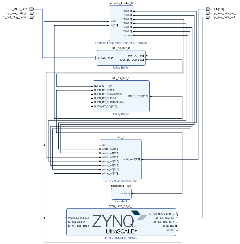
Block Design
| Scroll Title | ||||
|---|---|---|---|---|
| ||||
 |
PS Interfaces
| Page properties | ||||
|---|---|---|---|---|
| ||||
Note:
|
Activated interfaces:
...
| anchor | Table_PSI |
|---|---|
| title | PS Interfaces |
...
|
Control:
- User LED Control (D16, D15)
Monitoring:
- MGT CLK Measurement:
- Open Vivado HW-Manager and add VIO signal to dashboard (*.ltx located on prebuilt folder).Set radix from VIO signals to unsigned integer.Note: Frequency Counter is inaccurate and displayed unit is Hz
- Default B229_CLK1: 78,8MHz, B128_CLK1: 150MHz, B129_CLK1: 175MHz, B130_CLK1: 200MHz, B228_CLK1: 125MHz, B23ß_CLK1: 100MHz
| Scroll Title | ||||
|---|---|---|---|---|
| ||||
|
System Design - Vivado
| Page properties | ||||
|---|---|---|---|---|
| ||||
Note:
|
Block Design
| Scroll Title | ||||
|---|---|---|---|---|
| ||||
|
PS Interfaces
| Page properties | ||||
|---|---|---|---|---|
| ||||
Note:
|
Activated interfaces:
| Scroll Title | ||||||||||||||||||||
|---|---|---|---|---|---|---|---|---|---|---|---|---|---|---|---|---|---|---|---|---|
| ||||||||||||||||||||
|
...
|
Constrains
Basic module constrains
...
| Code Block | ||||
|---|---|---|---|---|
| ||||
# GT Clocks
#B128-1
set_property PACKAGE_PIN N27 [get_ports {PL_MGT_CLK_clk_p[0]}]
#B129-1
set_property PACKAGE_PIN J27 [get_ports {PL_MGT_CLK_clk_p[1]}]
#B228-1
set_property PACKAGE_PIN J8  [get_ports {PL_MGT_CLK_clk_p[2]}]
#B130-1
set_property PACKAGE_PIN E27 [get_ports {PL_MGT_CLK_clk_p[3]}]
#B229-1
set_property PACKAGE_PIN E8  [get_ports {PL_MGT_CLK_clk_p[4]}]
#B230-1
set_property PACKAGE_PIN B10 [get_ports {PL_MGT_CLK_clk_p[5]}]

## DP
set_property PACKAGE_PIN AB1 [get_ports dp_aux_data_in]
set_property PACKAGE_PIN V9 [get_ports dp_hot_plug_detect]
set_property PACKAGE_PIN AA8 [get_ports dp_aux_data_out]
set_property PACKAGE_PIN AA3  [get_ports dp_aux_data_oe_n]
set_property IOSTANDARD LVCMOS18 [get_ports dp_*]
## LED
set_property PACKAGE_PIN K14 [get_ports {LED[0]}]
set_property PACKAGE_PIN K10 [get_ports {LED[1]}]
set_property IOSTANDARD LVCMOS18 [get_ports {LED*}]
|
Software Design - SDK/HSI
| Page properties | ||||
|---|---|---|---|---|
| ||||
Note:
|
For SDK project creation, follow instructions from:
Application
...
set_property PACKAGE_PIN K10 [get_ports {LED[1]}]
set_property IOSTANDARD LVCMOS18 [get_ports {LED*}]
|
Software Design - Vitis
| Page properties | ||||
|---|---|---|---|---|
| ||||
Note:
|
For SDK project creation, follow instructions from:
Application
SDK template in ./sw_lib/sw_apps/ available.
| Page properties | ||||
|---|---|---|---|---|
| ||||
---------------------------------------------------------- FPGA Example scuMCS Firmware to configure SI5338 and Reset System. srec_spi_bootloaderTE modified 2019.2 SREC Bootloader to load app or second bootloader from flash into DDR Descriptions:
xilisf_v5_11TE modified 2019.2 xilisf_v5_11
---------------------------------------------------------- Zynq Example: zynq_fsblTE modified 2019.2 FSBL General:
Module Specific:
zynq_fsbl_flashTE modified 2019.2 FSBL General:
ZynqMP Example: ---------------------------------------------------------- zynqmp_fsblTE modified 2019.2 FSBL General:
Module Specific:
zynqmp_fsbl_flashTE modified 2019.2 FSBL General:
zynqmp_pmufwXilinx default PMU firmware. ---------------------------------------------------------- General Example: hello_te0820Hello TE0820 is a Xilinx Hello World example as endless loop instead of one console output. u-bootU-Boot.elf is generated with PetaLinux. Vitis is used to generate Boot.bin. |
zynqmp_fsbl
TE modified 20182019.2 FSBL
ChangesGeneral:
- Si5345Configuration
- see xfsbl_board.c and xfsbl_board.h, xfsbl_main.c
- Add Si5345-Registers.h, si5345.c, si5345.h, si5338.c, si5338.h, register_map.h
...
- Modified Files: xfsbl_main.c, xfsbl_hooks.h/.c, xfsbl_board.h/.c(search for 'TE Mod' on source code)
- Add Files: te_xfsbl_hooks.h/.c (for hooks and board)\n\
- General Changes:
- Display FSBL Banner and Device Name
Module Specific:
- Add Files: all TE Files start with te_*
- Si5338 and SI5345 Configuration
- PCIe reset
zynqmp_fsbl_flash
TE modified 20182019.2 FSBL
General:
- Modified Files: xfsbl_initialisation.c, xfsbl_hw.h, xfsbl_handoff.c, xfsbl_main.c
- General Changes:
- Display FSBL Banner
- Set FSBL Boot Mode to JTAG
- Disable Memory initialisation
Note: Remove compiler flags "-Os -flto -ffat-lto-objects" on 2018.2 SDK to generate FSBL
zynqmp_pmufw
Xilinx default PMU firmware.
...
Hello TEB0911 is a Xilinx Hello World example as endless loop instead of one console output.
u-boot
U-Boot.elf is generated with PetaLinux. SDK/HSI is used to generate Boot.bin.
...
For PetaLinux installation and project creation, follow instructions from:
Config
from:
Config
Start with petalinux-config or petalinux-config --get-hw-description
ChangesActivate:
- SUBSYSTEM_PRIMARY_SD_PSU_SD_1_SELECT
- CONFIG_SUBSYSTEM_ETHERNET_PSU_ETHERNET_3_MAC=""
U-Boot
Change platform-top.h
| Code Block | ||
|---|---|---|
| ||
#include <configs/platform-auto.h>
#define CONFIG_SYS_BOOTM_LEN 0xF000000

#define DFU_ALT_INFO_RAM \
                "dfu_ram_info=" \
        "setenv dfu_alt_info " \
        "image.ub ram $netstart 0x1e00000\0" \
        "dfu_ram=run dfu_ram_info && dfu 0 ram 0\0" \
        "thor_ram=run dfu_ram_info && thordown 0 ram 0\0"

#define DFU_ALT_INFO_MMC \
        "dfu_mmc_info=" \
        "set dfu_alt_info " \
        "${kernel_image} fat 0 1\\\\;" \
        "dfu_mmc=run dfu_mmc_info && dfu 0 mmc 0\0" \
        "thor_mmc=run dfu_mmc_info && thordown 0 mmc 0\0"

/*Required for uartless designs */
#ifndef CONFIG_BAUDRATE
#define CONFIG_BAUDRATE 115200
#ifdef CONFIG_DEBUG_UART
#undef CONFIG_DEBUG_UART
#endif
#endif

/*Define CONFIG_ZYNQMP_EEPROM here and its necessaries in u-boot menuconfig if you had EEPROM memory. */
#ifdef CONFIG_ZYNQMP_EEPROM
#define CONFIG_SYS_I2C_EEPROM_ADDR_LEN  1
#define CONFIG_CMD_EEPROM
#define CONFIG_ZYNQ_EEPROM_BUS          5
#define CONFIG_ZYNQ_GEM_EEPROM_ADDR     0x54
#define CONFIG_ZYNQ_GEM_I2C_MAC_OFFSET  0x20
#endif
|
Device Tree
Start with petalinux-config -c u-boot
Changes:
- CONFIG_ENV_IS_NOWHERE=y
- # CONFIG_ENV_IS_IN_SPI_FLASH is not set
- CONFIG_I2C_EEPROM=y
- CONFIG_ZYNQ_GEM_I2C_MAC_OFFSET=0xFA
- CONFIG_SYS_I2C_EEPROM_ADDR=0x54
- CONFIG_SYS_I2C_EEPROM_BUS=5
- CONFIG_SYS_EEPROM_SIZE=256
- CONFIG_SYS_EEPROM_PAGE_WRITE_BITS=0
- CONFIG_SYS_EEPROM_PAGE_WRITE_DELAY_MS=0
- CONFIG_SYS_I2C_EEPROM_ADDR_LEN=1
- CONFIG_SYS_I2C_EEPROM_ADDR_OVERFLOW=0
Change platform-top.h
| Code Block | ||
|---|---|---|
| ||
Device Tree
| Code Block | ||
|---|---|---|
| ||
/include/ "system-conf.dtsi"
/ {
  chosen {
    xlnx,eeprom = &eeprom;
  };
};

/* USB  */

&dwc3_0 {
    status = "okay";
    dr_mode = "host";
    snps,usb3_lpm_capable;
    snps,dis_u3_susphy_quirk;
    snps,dis_u2_susphy_quirk;
    phy-names = "usb2-phy","usb3-phy";
    phys = <&lane1 4 0 1 100000000>;
    maximum-speed = "super-speed";
};
| ||
| Code Block | ||
| ||
/include/ "system-conf.dtsi" / { }; /* USB */ &dwc3_0 { status = "okay"; dr_mode = "host"; }; /* QSPI */ &qspi { #address-cells = <1>; #size-cells = <0>; status = "okay"; flash0: flash@0 { compatible = "jedec,spi-nor"; reg = <0x0>; #address-cells = <1>; #size-cells = <1>; }; }; /* ETH */ &gem3 { phy-handle = <&phy0>; phy0: phy0@1 { device_type = "ethernet-phy"; reg = <1>; }; }; /* SD1 */ &sdhci1 { // disable-wp; no-1-8-v; }; &i2c0 { i2cswitch@76 { // I2C Switch U13 compatible = "nxp,pca9548"; #address-cells = <1>; #size-cells = <0>; reg = <0x76>; i2c-mux-idle-disconnect; i2c@2 { // FMCD (/dev/i2c-3) #address-cells = <1>; #size-cells = <0>; reg = <2>; }; i2c@3 { // FMCE (/dev/i2c-4) #address-cells = <1>; #size-cells = <0>; reg = <3>; }; i2c@4 { // FMCB (/dev/i2c-5) #address-cells = <1>; #size-cells = <0>; reg = <4>; }; i2c@5 { // FMCC (/dev/i2c-6) #address-cells = <1>; #size-cells = <0>; reg = <5>; }; i2c@6 { // PLL (/dev/i2c-7) #address-cells = <1>; #size-cells = <0>; reg = <6>; si570_2: clock-generator3@5d { #clock-cells = <0>; compatible = "silabs,si570"; reg = <0x5d>; temperature-stability = <50>; factory-fout = <156250000>; clock-frequency = <78800000>; }; }; }; i2cswitch@77 { // I2C Switch U37 compatible = "nxp,pca9548"; #address-cells = <1>; #size-cells = <0>; reg = <0x77>; i2c-mux-idle-disconnect; i2c@0 { // SFP2 (/dev/i2c-9) #address-cells = <1>; #size-cells = <0>; reg = <0>; }; i2c@1 { // FMCA (/dev/i2c-10) #address-cells = <1>; #size-cells = <0>; reg = <1>; }; i2c@2 { // FMCF (/dev/i2c-11) #address-cells = <1>; #size-cells = <0>; reg = <2>; }; i2c@3 { // SFP0 (/dev/i2c-12) #address-cells = <1>; #size-cells = <0>; reg = <3>; }; i2c@4 { // SFP1 (/dev/i2c-13) #address-cells = <1>; #size-cells = <0>; reg = <4>; }; i2c@5 { // MEM (/dev/i2c-14) // Low frequency to work with CPLD clock-frequency = <100000>; #address-cells = <1>; #size-cells = <0>; reg = <5>; eeprom: eeprom@54 { compatible = <1>; "atmel,24c08"; #size-cellsreg = <0><0x54>; reg = <5>}; }; i2c@6 { // DDR4 (/dev/i2c-15) #address-cells = <1>; #size-cells = <0>; reg = <6>; }; i2c@7 { // USBH (/dev/i2c-16) #address-cells = <1>; #size-cells = <0>; reg = <7>; }; }; }; /* UNUSED DMA disable */ &lpd_dma_chan1 { status = "disabled"; }; &lpd_dma_chan2 { status = "disabled"; }; &lpd_dma_chan3 { status = "disabled"; }; &lpd_dma_chan4 { status = "disabled"; }; &lpd_dma_chan5 { status = "disabled"; }; &lpd_dma_chan6 { status = "disabled"; }; &lpd_dma_chan7 { status = "disabled"; }; &lpd_dma_chan8 { status = "disabled"; }; |
Kernel
Deactivate:
CONFIG_CPU_IDLE (only needed to fix JTAG Debug issue)
CONFIG_CPU_FREQ (only needed to fix JTAG Debug issue)
Rootfs
Activate:
- i2c-tools
Applications
|
Kernel
Start with petalinux-config -c kernel
Changes:
- # CONFIG_CPU_IDLE is not set (only needed to fix JTAG Debug issue)
- # CONFIG_CPU_FREQ is not set (only needed to fix JTAG Debug issue)
- CONFIG_EDAC_CORTEX_ARM64=y (only needed to fix JTAG Debug issue)
- CONFIG_NVME_CORE=y
- CONFIG_BLK_DEV_NVME=y
- # CONFIG_NVME_MULTIPATH is not set
- CONFIG_NVME_TARGET=y
- # CONFIG_NVME_TARGET_LOOP is not set
- # CONFIG_NVME_TARGET_FC is not set
- CONFIG_NVM=y
- CONFIG_NVM_PBLK=y
- CONFIG_NVM_PBLK_DEBUG=y
Rootfs
Start with petalinux-config -c rootfs
Changes:
- CONFIG_i2c-tools=y
- CONFIG_busybox-httpd=y (for web server app)
- CONFIG_packagegroup-petalinux-utils(util-linux,cpufrequtils,bridge-utils,mtd-utils,usbutils,pciutils,canutils,i2c-tools,smartmontools,e2fsprogs)
Applications
See: \os\petalinux\project-spec\meta-user\recipes-apps\
startup
Script App to load init.sh from SD Card if available.
webfwu
Webserver application accemble for Zynq access. Need busybox-httpdSee: \os\petalinux\project-spec\meta-user\recipes-apps\startup\files
Additional Software
| Page properties | ||||
|---|---|---|---|---|
| ||||
| Note: |
...
File location <design name>/misc/Si5338/RegisterMapSi5338-*.txtslabtimeproj
General documentation how you work with these project will be available on Si5338
...
| Scroll Title | |||||||||||||||||||||||||||||||||||||||||||||||||||||||||||||||||||||||||||||||||||||||||||||||||||||||||||||||||||||||
|---|---|---|---|---|---|---|---|---|---|---|---|---|---|---|---|---|---|---|---|---|---|---|---|---|---|---|---|---|---|---|---|---|---|---|---|---|---|---|---|---|---|---|---|---|---|---|---|---|---|---|---|---|---|---|---|---|---|---|---|---|---|---|---|---|---|---|---|---|---|---|---|---|---|---|---|---|---|---|---|---|---|---|---|---|---|---|---|---|---|---|---|---|---|---|---|---|---|---|---|---|---|---|---|---|---|---|---|---|---|---|---|---|---|---|---|---|---|---|---|
| |||||||||||||||||||||||||||||||||||||||||||||||||||||||||||||||||||||||||||||||||||||||||||||||||||||||||||||||||||||||
2020-06-03 | v.10 | John Hartfiel |
2020-03-25 | v.9 | John Hartfiel |
2020-02-24 | v.8 | John Hartfiel |
2020-02-13 | v7 | John Hartfiel |
2019-02-07 | v.6 | John Hartfiel |
2018-11-26 v.5 | John Hartfiel |
2018-07-20 v.4 | John Hartfiel |
2018-07-20 | v.1 | John Hartfiel |
-- | all |
-- | |
...
Overview
Content Tools