...
| Scroll Title |
|---|
| anchor | Figure_OV_BD |
|---|
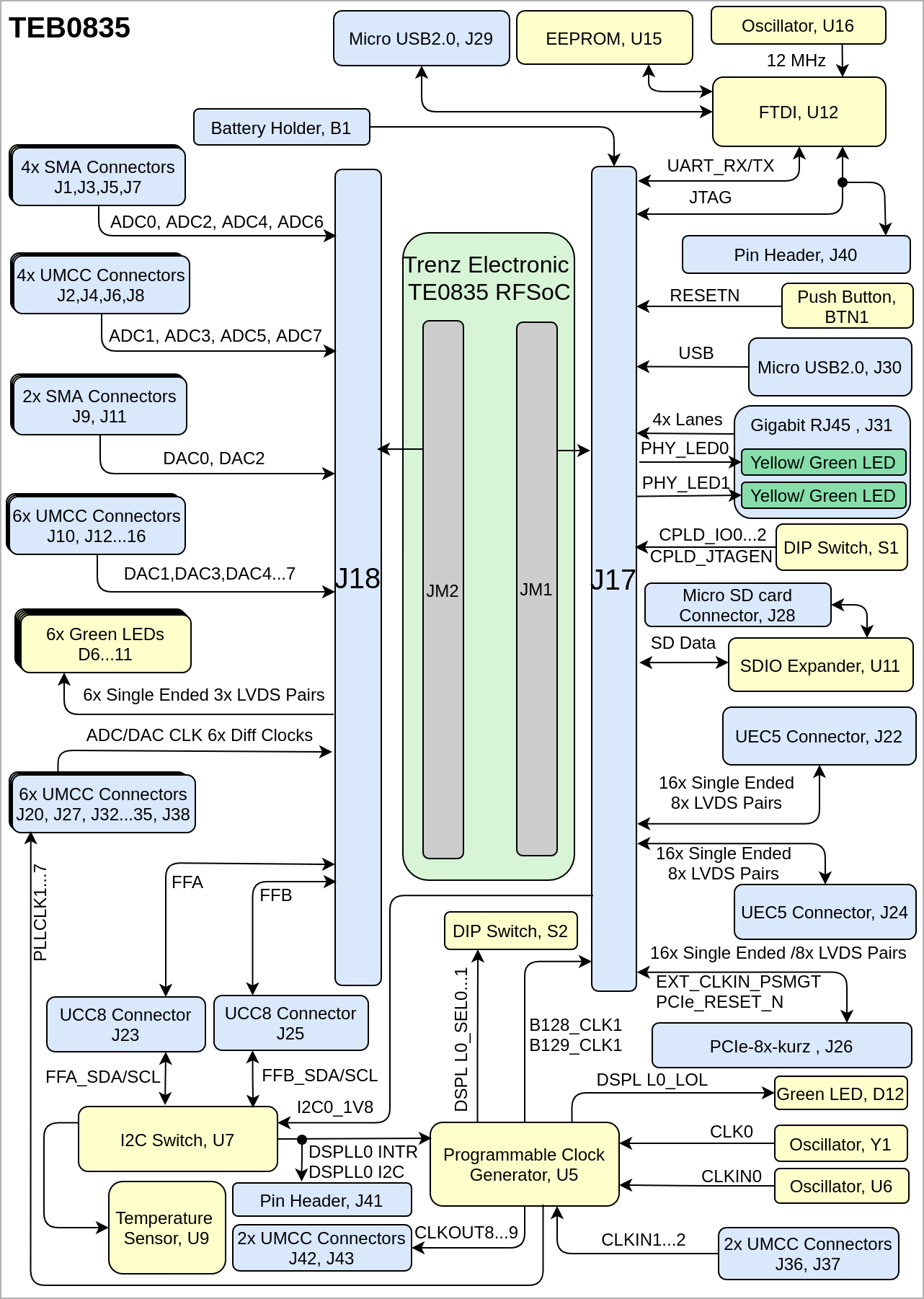
| title | TEB0835 block diagram |
|---|
|
| Scroll Ignore |
|---|
| draw.io Diagram |
|---|
| border | false |
|---|
| viewerToolbar | true |
|---|
| |
|---|
| fitWindow | false |
|---|
| diagramDisplayName | |
|---|
| lbox | true |
|---|
| revision | 910 |
|---|
| diagramName | TEB0835_OV_BD |
|---|
| simpleViewer | false |
|---|
| width | |
|---|
| links | auto |
|---|
| tbstyle | hidden |
|---|
| diagramWidth | 635641 |
|---|
|
|
| Scroll Only |
|---|

|
|
Main Components
...
| Scroll Title |
|---|
| anchor | Figure_OV_MC |
|---|
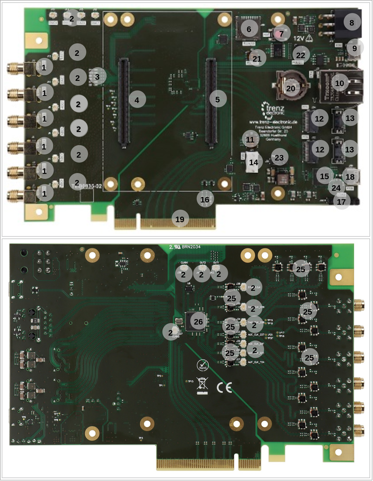
| title | TEB0835 main components |
|---|
|
| Scroll Ignore |
|---|
| draw.io Diagram |
|---|
| border | false |
|---|
| viewerToolbar | true |
|---|
| |
|---|
| fitWindow | false |
|---|
| diagramDisplayName | |
|---|
| lbox | true |
|---|
| revision | 45 |
|---|
| diagramName | TEB0835_OV_MC |
|---|
| simpleViewer | false |
|---|
| width | |
|---|
| links | auto |
|---|
| tbstyle | hidden |
|---|
| diagramWidth | 641 |
|---|
|
|
| Scroll Only |
|---|

|
|
- SMA Connectors, J1,J3,J5,J7,J9,J11
- U.FL (UMCC) Connectors, J2,J4,J6,J8, J10, J12...16
- Green LEDs, D6...11
- B2B Connector, J18
- B2B Connector, J17
- Micro SD Card Connector, J28
- Reset Push Button, BTN1BTN1ee
- Mosfet Transistors
- PCIe Connector, J19
- Micro USB2.0 Connectors, J29-J30
- Gigabit RJ45 Connector, J31
- DIP Switch, S1
- UEC5 Connector, J22,J24
- UCC8 Connector, J23,J25
- 4x1 Pin Header, J21
- FTDI, U12
- Green LEDs, D1...3
- 4x1 Pin Header, J20
- EEPROM, U15
- PCIe Card, J26
...
| Scroll Title |
|---|
| anchor | Table_OV_BP |
|---|
| title | Boot process. |
|---|
|
| Scroll Table Layout |
|---|
| orientation | portrait |
|---|
| sortDirection | ASC |
|---|
| repeatTableHeaders | default |
|---|
| style | |
|---|
| widths | |
|---|
| sortByColumn | 1 |
|---|
| sortEnabled | false |
|---|
| cellHighlighting | true |
|---|
|
MODE Signal State | |Boot Mode |
|---|
--- | ---- |
|
| Scroll Title |
|---|
| anchor | Table_OV_RST |
|---|
| title | Reset process. |
|---|
|
| Scroll Table Layout |
|---|
| orientation | portrait |
|---|
| sortDirection | ASC |
|---|
| repeatTableHeaders | default |
|---|
| style | |
|---|
| widths | |
|---|
| sortByColumn | 1 |
|---|
| sortEnabled | false |
|---|
| cellHighlighting | true |
|---|
|
Signal | B2B | I/O | Note |
|---|
RESETN | J17- 36 | Input | Connected to Push Button, BTN1 |
|
...
| Scroll Title |
|---|
| anchor | Table_SIP_PCIe |
|---|
| title | PCIe-x8-Kurz Connectors |
|---|
|
| Scroll Table Layout |
|---|
| orientation | portrait |
|---|
| sortDirection | ASC |
|---|
| repeatTableHeaders | default |
|---|
| style | |
|---|
| widths | |
|---|
| sortByColumn | 1 |
|---|
| sortEnabled | false |
|---|
| cellHighlighting | true |
|---|
|
| Signal Name | Connected to | Note |
|---|
| B505_RX0...3 | B2B, J17 | 8x Single Ended/ 4x LVDS Pairs | | B505_TX0...3 | B2B, J17 | 8x Single Ended/ 4x LVDS Pairs | | EXT_CLKIN_PSMGT | B2B, J17 |
| | PCIE_RSTB_R | B2B, J17 | Pulled up to 1.8V |
|
MIO Pins
| Page properties |
|---|
|
you must fill the table below with group of MIOs which are connected to a specific components or peripherals, you do not have to specify pins in B2B, Just mention which B2B is connected to MIOs. The rest is clear in the Schematic.
Example:
| MIO Pin | Connected to | B2B | Notes |
|---|
| MIO12...14 | SPI_CS , SPI_DQ0... SPI_DQ3 SPI_SCK | J2 | QSPI |
| Scroll Title |
|---|
| anchor | Table_SIP_MIOs |
|---|
| title | MIOs pins |
|---|
|
| Scroll Table Layout |
|---|
|
| orientation | portrait |
|---|
| sortDirection | ASC |
|---|
| repeatTableHeaders | default |
|---|
style | widths | | sortByColumn | 1 |
|---|
| sortEnabled | false |
|---|
| cellHighlighting | true |
|---|
| MIO Pin | Connected to | B2B | Notes |
|---|
| MIO0...12 | SPI FLash, U24-U25 | - | Dual SPI FLash |
| MIO13 | LED Green, D1 | - | 3.3V_CPLD |
| MIO14...25 | FPGA Bank 500,U1 | J1 | PSMIO |
| MIO26...27 | FPGA Bank 501,U1 | J1 | PSMIO |
| MIO28...29 | CPLD, U31 | - | UART_TX, UART_RX |
| MIO30...31 | FPGA Bank 501, U1 | J1 | PSMIO |
| MIO32...33 | EEPROM,U23 | - | I2C_SCL, I2C_SDA |
| MIO34...35 | FPGA Bank 501,U1 | J1 | PSMIO |
| MIO36 | Gigabit ETH, U20 | - | ETH_RST |
| MIO37 | USB2.0, U11 | - | USB_RST |
| MIO38...51 | FPGA Bank 501, U1 | J1 | PSMIO |
| MIO52...62 | USB2.0, U11 | - | USB |
MIO63...77 | Gigabit ETH, U20 | - | ETH
Test Points
| Page properties |
|---|
|
you must fill the table below with group of Test Point which are indicated as TP in a schematic. If there is no Test Point remarked in the schematic, delet the Test Point section. Example: | Test Point | Signal | B2B | Notes |
|---|
| 10 | PWR_PL_OK | J2-120 |
|
|
...
| Scroll Title |
|---|
| anchor | Table_OBP |
|---|
| title | On board peripherals |
|---|
|
| Scroll Table Layout |
|---|
| orientation | portrait |
|---|
| sortDirection | ASC |
|---|
| repeatTableHeaders | default |
|---|
| style | |
|---|
| widths | |
|---|
| sortByColumn | 1 |
|---|
| sortEnabled | false |
|---|
| cellHighlighting | true |
|---|
|
|
EEPROM
| Scroll Title |
|---|
| anchor | Table_OBP_EEP |
|---|
| title | I2C EEPROM interface MIOs and pins |
|---|
|
| Scroll Table Layout |
|---|
| orientation | portrait |
|---|
| sortDirection | ASC |
|---|
| repeatTableHeaders | default |
|---|
| style | |
|---|
| widths | |
|---|
| sortByColumn | 1 |
|---|
| sortEnabled | false |
|---|
| cellHighlighting | true |
|---|
|
| Pin | Schematic | Connected to | Notes |
|---|
| CS | EECS | FTDI, U12 |
| | CLK | EECLK | FTDI, U12 |
| | DIN | EEDATA | FTDI, U12 |
|
|
...

