Page History
JTAG signals are available at:
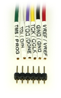
- available on the gender-inverted standard 6-pin JTAG header connector J2 as shown in the figure below.;
- available at B2B connector JM4. See Table 40 for additional information on these signals.
JTAG Connector J2
| Scroll pdf title | ||
|---|---|---|
| ||
|

To connect your computer to JTAG connector J2, you typically need
- a JTAG cable with standard 6-pin JTAG female header;
- a 2.54 mm pitch 1 × 6 pin gender changer header.
Some examples of JTAG cable set are listed in the table below.
| Scroll pdf title | ||||||||||||||||||||||||
|---|---|---|---|---|---|---|---|---|---|---|---|---|---|---|---|---|---|---|---|---|---|---|---|---|
| ||||||||||||||||||||||||
|
Figure A below shows a standard 6-pin JTAG female header, in this case flying leads, with a gender changer header.
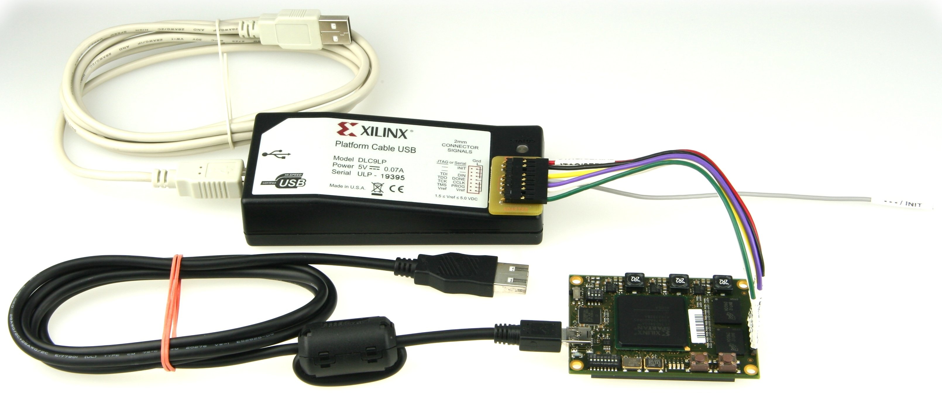
Figure B below shows how a JTAG cable, in this case a Xilinx Platform Cable USB with flying leads and gender changer, is connected to a TE0320.
| Scroll pdf title | ||
|---|---|---|
| ||
|
...
|

...
The figure below shows a recommended set-up for TE0320 configuration and operation. The USB cable provides for power supply and data communication channel. The JTAG is ideal for quick configuration and effective debugging.
| Scroll pdf title | ||
|---|---|---|
| ||
 |
JTAG lines at B2B connector JM4
JTAG signal lines are also available at B2B connector JM4 (pins 74, 76, 78 and 80). See the corresponding pin-out table for additional information on these signals.
Overview
Content Tools