| Page properties |
|---|
|
- Module: TRM Name always "TE Series Name" +TRM
Example: "TE0728 TRM"
Template Change history: | Date | Version | Changes | Author |
|---|
| 4.2 | | ED |
| 4.1 | | ED |
| 4.0 | - Rework for smaller TRM which can be generated faster
- Reduce Signal Interfaces Pin
- Reduce On Board Perihery
- Reduce Power
- Move Configuration Signals from Overview to own section
| JH |
| 3.12 | - Version History
- changed from list to table
- all
- changed title-alignment for tables from left to center
| ma |
| 3.11 | - update "Recommended Operating Conditions" section
|
|
| 3.1 | - New general notes for temperature range to "Recommended Operating Conditions"
|
|
| 3.02 | - add again fix table of content with workaround to use it for pdf and wiki
- Export Link for key features examples
- Notes for different Types (with and without Main FPGA)
- Export Link for Signals, Interfaces and Pins examples
- Notes for different Types (Modul, Modul Hypride, Evalboard, Carrier)
|
|
| 3.01 | - remove fix table of content and page layout ( split page layout make trouble with pdf export)
- changed and add note to signal and interfaces, to on board periphery section
- ...(not finished)
|
|
| 3.00 | - → separation of Carrier/Module and evaluation kit TRM
|
|
| 2.15 | - add excerpt macro to key features
|
|
| 2.14 | - add fix table of content
- add table size as macro
|
|
|
| Page properties |
|---|
|
Important General Note:
|
| Page properties |
|---|
|
----------------------------------------------------------------------- |
| Page properties |
|---|
|
Note for Download Link of the Scroll ignore macro: |
Overview
The Trenz Electronic TE0950-02 is a powerful adaptive SoC evaluation board, equipped with an AMD Versal™ AI (Edge) device. Furthermore, the board is equipped with up to 8GB DDR4 SDRAM, 128 MByte SPI Flash and an eMMC for configuration and data storage as well as powerful switching power supplies for all required voltages. Inputs and outputs are provided by robust, flexible and cost-effective high-speed connectors.
Refer to http://trenz.org/te0950-info for the current online version of this manual and other available documentation.
Key Features
| Excerpt |
|---|
- SoC
- AMD Versal™ AI device 1)
- Package: A784
- Device: VE2002, VE2102, VE2202, VE2302, VM1102 1)
- Speed: -1, -2, -3 1)
- Temperature: I, E 1)
- RAM/Storage
- DDR4 SDRAM
- Data width: 64bit
- Size: def. 8GB, up to 8 GByte possible 1)
- Speed: up to 3200Mb/s 2)
- 128 MByte SPI Flash (primary boot option)
- Data width: 8bit
- size: def. 128MB, up to 512MB possible 1)
- MicroSD card (primary boot option)
- e.MMC (secondary boot option) 1)
- Data width: 8bit
- size: def. 32GB 1)
- EEPROM with MAC-address
- On Board
- AMD Artix™ 7 FPGA as configurable Levelshifter/MUX for FMC and other 3.3 V IOs
- 32 MByte SPI Flash
- 1 dip switch
- 2 LEDs
- USB 2.0 Host/Device/OTG (type Micro A/B connector)
- USB JTAG + UART Micro-USB B
- Gigabit Ethernet RJ45
- Output
- Input
- 1 push button (PL)
- 2 dip switches (2 x MIO)
- Reset button
- Interface
- zQSFP
- 2 x CRUVI HS
- each optimized for 4 Lane MIPI, one with reduced pinout
- 2 x CRUVI LS
- CSI-2 connector
- optimized for camera, 2 lane MIPI
- FMC
- 4 GTYP Transceiver
- 34 LA diff pairs to Levelshifter/MUX
- Power
- Dimension
- Notes
- 1) depends on assembly version
- 2) depends on used DDR4
- 3) productions within 2023 are equipped with engineering samples (AMD Vivado ES licence needed)
|
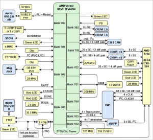
Block Diagram
| Page properties |
|---|
|
| Note |
|---|
Title (not anchor) of all Scroll Title such as DrawIOs and Tables should be changed according to the Module name. Example: TE0812 Block Diagram |
| Note |
|---|
All created DrawIOs should be named according to the Module name: Example: DrawIO of TE0812 Block Diagram should be named TE0812_OV_BD |
|
| Scroll Title |
|---|
| anchor | Figure_OV_BD |
|---|
| title-alignment | center |
|---|
| title | TE0950 block diagram |
|---|
|
| Scroll Ignore |
|---|
| draw.io Diagram |
|---|
| border | false |
|---|
| |
|---|
| diagramName | Figure_OV_BD |
|---|
| simpleViewer | false |
|---|
| width | |
|---|
| links | auto |
|---|
| tbstyle | top |
|---|
| diagramDisplayName | |
|---|
| lbox | false |
|---|
| diagramWidth | 701 |
|---|
| revision | 4 |
|---|
|
|
| Scroll Only |
|---|
|
|
Main Components
| Page properties |
|---|
|
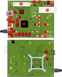
Notes : - Picture of the PCB (top and bottom side) with labels of important components
- Add List below
|
| Scroll Title |
|---|
| anchor | Figure_OV_MC |
|---|
| title-alignment | center |
|---|
| title | TE0950 main components |
|---|
|
| Scroll Ignore |
|---|
| draw.io Diagram |
|---|
| border | false |
|---|
| |
|---|
| diagramName | Figure_OV_MC |
|---|
| simpleViewer | false |
|---|
| width | |
|---|
| links | auto |
|---|
| tbstyle | top |
|---|
| diagramDisplayName | |
|---|
| lbox | false |
|---|
| diagramWidth | 897 |
|---|
| revision | 6 |
|---|
|
|
| Scroll Only |
|---|
|
|
- SoC (Versal) U1
- DDR4 U8, U9, U10, U11
- eMMC U25
- dual QSPI Configuration Flash (Versal) U23, U24
- ETH Phy U31
- MAC EEPROM U35
- USB 2.0 Phy U27
- Jumper (USB Device/Host/OTG) J5
- Artix FPGA (Levelshifter/MUX for FMC IOs) U13
- OSPI Configuration Flash (Artix) U14
- FTDI JTAG/UART to USB Bridge U15
- FTDI Configuration EEPROM U17
- zQSFP U12/J1
- LPC FMC J3
- CRUVI HS J10, J11
- CRUVI LS J12, J13
- CSI CAM Connector J15
- SD-CARD Slot J4
- RJ45 ETH jack J9
- micro USB A/B Connector J8
- micro USB B Connector (JTAG/UART) J2
- 4 Pin FAN Connector J17
- Power Input Jack J14
- Reset Push Button S3
- User Push Button S1
- Dip Switches (JTAG Selection) S4
- Dip Switches (Bootmode, User) S2
- Dip Switches (FMC VADJ Selection, User) S5
- LEDs (Power) D8, D9, D10
- LEDs (Status/User) D0, D1, D2, D3 D4, D6, D11
- 1x6 JTAG Header J18 (optional)
Initial Delivery State
| Page properties |
|---|
|
| Note |
|---|
Only components like EEPROM, QSPI flash can be initialized by default at manufacture. If there is no components which might have initial data ( possible on carrier) you must keep the table empty |
|
| Scroll Title |
|---|
| anchor | Table_OV_IDS |
|---|
| title-alignment | center |
|---|
| title | Initial delivery state of programmable devices on the module |
|---|
|
| Scroll Table Layout |
|---|
| orientation | portrait |
|---|
| sortDirection | ASC |
|---|
| repeatTableHeaders | default |
|---|
| sortByColumn | 1 |
|---|
| sortEnabled | false |
|---|
| cellHighlighting | true |
|---|
|
Storage device name | Content | Notes |
|---|
| DDR4 SDRAM | not programmed |
| | eMMC | not programmed |
| dual Quad SPI Flash (Versal) | not programmed |
| | MAC EEPROM | not programmed besides factory programmed MAC address |
| | FTDI EEPROM | FTDI configuration for JTAG/UART with AMD Vivado compatible license |
| | Quad SPI Flash (Artix) | Template Design with basic functionality | Design has to be adapted to use case. |
|
Signals, Interfaces and Pins
Connectors
| Scroll Title |
|---|
| anchor | Table_SIP_C |
|---|
| title-alignment | center |
|---|
| title | Board Connectors |
|---|
|
| Scroll Table Layout |
|---|
| orientation | portrait |
|---|
| sortDirection | ASC |
|---|
| repeatTableHeaders | default |
|---|
| sortByColumn | 1 |
|---|
| sortEnabled | false |
|---|
| cellHighlighting | true |
|---|
|
| Connector Type | Designator | Interface | IO CNT | Notes |
|---|
| B2B | J3 | FMC | 4x MGT Transeiver
34 DIFF / 68 SE
4x CLK, CLKDIR, I2C, PG | MGTs tested with 15Gbps25.777Gbps (Maximum for speedgrade)
FMC LA pins from/to Artix. Artix FPGA has to be configured for use case.
CLK and management signals connected to Artix. | | B2B | J10 | CRUVI HS | 12 DIFF / 24 SE
4 SE
8 SE | Full pinout, MIPI 4 Lanes optimized (XPIO)
(XPIO)
connected to Artix @3.3V | | B2B | J11 | CRUVI HS | 9 DIFF / 18 SE
2 SE
8 SE | Reduced pinout, MIPI 4 Lanes optimized (XPIO) (XPIO)
connected to Artix @3.3V | | B2B | J12 | CRUVI LS | 8 SE | HD bank 302 @3.3V | | B2B | J13 | CRUVI LS | 8 SE | HD bank 302 @3.3V | | CON | J1, U12 | zQSFP | 4x MGT Transeiver
5 SE, I2C | MGTs tested with 15Gbps25.777Gbps (Maximum for speedgrade),
management signals connected to Artix. | | CON | J15 | CSI-2 CAM | 3 DIFF / 6 SE
4 SE | MIPI 2Lanes (XPIO),
(I2C and GPIO) to HD Bank 302 @3.3V | | CON | J9 | GB ETH | 4 DIFF | LPD | | CON | J8 | micro USB2.0 A/B | 1 DIFF | Host/Device/OTG set J5 according for HW configuration | | CON | J2 | micro USB2.0 B | 1 DIFF | JTAG/UART via FTDI | | CON | J4 | micro SD 2.0 | 7 SE | primary boot option, routed via levelshifter U26 | | CON | J17 | 4 pin FAN | 2 SE | For SoC FAN with Tacho and PWM signals connected to Artix. | | CON | J18 | JTAG | 4SE | not assembled, footprint compatible to 1x6 2,54mm pitch header |
|
Test Points
| Page properties |
|---|
|
you must fill the table below with group of Test Point which are indicated as TP in a schematic. If there is no Test Point remarked in the schematic, delete the Test Point section. Example: | Test Point | Signal | Notes1) |
|---|
| TP1 | PWR_PL_OK |
|
1) Direction: - IN: Input from the point of view of this board.
- OUT: Output from the point of view of this board.
|
| Scroll Title |
|---|
| anchor | Table_SIP_TPs |
|---|
| title-alignment | center |
|---|
| title | Test Points Information |
|---|
|
| Scroll Table Layout |
|---|
| orientation | portrait |
|---|
| sortDirection | ASC |
|---|
| repeatTableHeaders | default |
|---|
| sortByColumn | 1 |
|---|
| sortEnabled | false |
|---|
| cellHighlighting | true |
|---|
|
| Test Point | Signal | Notes1) |
|---|
TP32 | GND | GND | TP29 | 12V | 12V | | TP17 | 5V0 | 5V | | TP16 | 3V3 | 3.3V | | TP43, TP44 | GTYP_AVCC | 0.92V | | TP46, TP47 | GTYP_AVTT | 1.2V | | TP45 | GTYP_AVCC_AUX | 1.5V | | TP48 | A_3V3 | 3.3V | | TP19 | 1V0 | 1.0V | | TP42 | 3V3_FMC | 3.3V | | TP40 | FMC_VADJ | 1.2V, S5A-C: OFF,OFF, OFF
1.8V, S5A-C: ON,OFF, OFF
2.5V, S5A-C: ON,ON, OFF
3.3V, S5A-C: ON,ON, ON | | TP18 | 1V8 | 1.8V | | TP39 | V_VCCAUX | 1.5V | | TP41 | C_VADJ | 1.2V | | TP35 | DDR_1V2 | 1.2V | | TP33 | DDR_2V5 | 2.5V | | TP36 | DDR_VTT | 0.6V | TP37 | VREFA | 0.6V | | TP38 | V_VCC_SOC | 0.8V (low (L) and mid (M) voltage devices) 0.88V (high (H) voltage devices) | | TP34 | V_VCC_CORE | 0.7V (low (L) voltage devices)
0.8V (mid (M) voltage devices)
0.88V (high (H) voltage devices) | | TP1 | V_VCC_BATT | Input for VCC_BAT supply when R21 removed. Default (R21 assembled) GND. | | TP2 | V_FUSE | Input for V_FUSE supply when R43 removed. Default (R43 assembled) GND. | | TP3 | DDR4-TEN_0 | pulled-down to GND | | TP4 | DDR4-TEN1 | pulled-down to GND | | TP5 | DDR4-TEN2 | pulled-down to GND | | TP6 | DDR4-TEN3 | pulled-down to GND | | TP20 | PHY_LED2 | Function dependent on ETH PHY (U31) configuration. | | TP21 | I2C_PMC_SCL | @1.8V | | TP23 | I2C_PMC_SDA | @1.8V | | TP22 | DCDC_5V0_SCL | @3.3V Levelshifted I2C_PMC_SCL signal | | TP24 | DCDC_5V0_SDA | @3.3V Levelshifted I2C_PMC_SDA signal | | TP25 | I2C1_SCL | @1.8V | | TP26 | I2C1_SDA | @1.8V | | TP27 | I2C_SYSMON_SCL | @1.8V | | TP28 | I2C_SYSMON_SDA | @1.8V | | TP7 | TCK | JTAG TCK (Versal and Artix) | | TP12 | TMS | JTAG TCK (Versal and Artix) | | TP10 | V_TDO | JTAG TDO | | TP8 | FTDI_TDI | JTAG TDI | | TP9 | A_TDI | JTAG TDI Artix, connected to FTDI_TDI via DIP S4A | | TP11 | V_TDI | JTAG TDI Versal, connected to FTDI_TDI via DIP S4B | | TP13 | A_TDO | JTAG TDO Versal, connected to VTDI via DIP S4C | | TP14 | F_UART_TX | @3.3V, from Versal, levelshifted UART1_TX signal, to FTDI | | TP15 | F_UART_RX | @3.3V, from FTDI, levelshifted UART1_RX signal to Versal | | TP31 | - | Sense input of reset chip U38, connected to PG_GTYP_AVTT @3.3V via R203 | | TP30 | FAULTn_12V | @12V, Fault signal of input protection U37 |
|
On-board Peripherals
| Page properties |
|---|
|
Notes : In the on-board peripheral table "chip/Interface" must be linked to the corresponding chapter or subsection by assigning advance link using: #NameOfTheSection Example: | Chip/Interface | Designator | Connected To | Notes |
|---|
| ETH PHY | U10 | | Gigabit ETH PHY |
|
| Scroll Title |
|---|
| anchor | Table_OBP |
|---|
| title-alignment | center |
|---|
| title | On board peripherals |
|---|
|
| Scroll Table Layout |
|---|
| orientation | portrait |
|---|
| sortDirection | ASC |
|---|
| repeatTableHeaders | default |
|---|
| sortByColumn | 1 |
|---|
| sortEnabled | false |
|---|
| cellHighlighting | true |
|---|
|
| Chip/Interface | Designator | Connected To | Notes |
|---|
| Versal SoC | U1 | - | Engineering Sample | | DDR4 SDRAM | U8, U9, U10, U11 | Versal XPIO |
| | dual parallel QSPI | U23, U24 | Versal PMC/MIO | primary boot option optional instead OSPI at U23 and U24 not fitted, also some resistors have to be changed, compare schematics | | GB ETH PHY | U31 | Versal MIO |
| | USB PHY | U27 | Versal MIO | USB2.0 | | Oscillator | U4, U5 | Versal XPIO | 2x 200Mhz, DDR4 controller, User | | Oscillator | U6, U7 | Versal GTYP REFCLK | 156.25MHz, 125MHz, for QSFP MGTs. | | eMMC | U25 | Versal PMC/MIO | secondary boot option | | EEPROM | U35 |
| for MAC. I2C PS, Address 50H | | User Dip 3x | S2C, S2D | Versal MIO |
| | User LED 2x | D0
D1 | Versal MIO
Versal HD | both green | | Push Button | S1 | Versal HD |
| | Artix FPGA | U13 | - Versal XPIO
(14 DIFF / 28 SE) - FMC (J3) LA pins
- QSFP (J1, U12) config signals
- CRUVI HS (J10, J11) 3.3V signals
| Configurable levelshifter/MUX for FMC and other 3.3V periphery configuration signals | | QSPI | U14 | Artix | configuration Memory for Artix | | User LED 2x | D2, D3 | Artix | D2 green, D3 red | | User Dip | S5D | Artix |
|
|
Configuration and System Control Signals
| Page properties |
|---|
|
- Overview all Controller signals, like Reset, Boote Mode, JTAG Interface(Connector or USB In case of FTDI)...
- In case it's connected to CPLD always link to CPLD description and add not from the current implementation here(in case it's available)
|
| Scroll Title |
|---|
| anchor | Table_OV_CNTRL |
|---|
| title-alignment | center |
|---|
| title | Controller signal. |
|---|
|
| Scroll Table Layout |
|---|
| orientation | portrait |
|---|
| sortDirection | ASC |
|---|
| repeatTableHeaders | default |
|---|
| sortByColumn | 1 |
|---|
| sortEnabled | false |
|---|
| cellHighlighting | true |
|---|
|
| Component 'Label' | Signal Name | Direction1) | Description |
|---|
| LED D11 (red) 'ERROR' | V_ERROR | OUT | Versal Error → signal 'low' → LED 'ON' | | LED D4 (red) 'DONE' | V_DONE | OUT | Versal configuration Done → signal 'high' → LED 'OFF' | | Dip switch S2A 'BOOT' | V_MODE1 | IN | Select primary boot mode:
JTAG QSPI32 SD card (SD1 2.0) OSPI
OFF ON OFF OFF
OFF OFF ON OFF
OFF OFF OFF ON | | Dip switch S2B 'BOOT' | V_MODE02 | IN | | Dip switch S2C 'BOOT' | V_MODE3 | IN | | DIP switch S4A 'JTAG' | FTDI_TDI, A_TDI | IN | Select JTAG:
Artix-Versal in chain, Versal only
ON, OFF
OFF, ON
ON, OFF | | DIP switch S4B 'JTAG' | FTDI_TDI, V_TDI | IN | | DIP switch S4C 'JTAG' | A_TDO, V_TDI | IN | | LED D6 (red) 'DONE' | A_DONE | OUT | Artix configuration Done → signal 'high' → LED 'OFF' | | LED D7 (green) 'UART' | F_UART_LED | OUT | UART activity → signal 'low' → LED 'ON' | | Push button S3 'RESET' | MR | IN | On press resets configuration of Versal and Artix by pulling V_POR_B, A_PROG_B signals via reset chip U38 low. | | LED D9 (green) '12V' | 12V | OUT | 'ON' when 12V after power protection available | | LED D8 (green) '5V' | 5V0 | OUT | 'ON' when 5V are available | | LED D10 (green) '3.3V_FMC' | 3V3_FMC | OUT | 'ON' when 3.3V_FMC available | | DIP switch S5A 'FMC_VADJ' | FB_FMC_VADJ | IN | Select FMC_VADJ: 1.2V 1.8V 2.5V 3.3V
OFF ON ON ON
OFF OFF ON ON
OFF OFF OFF ON | | DIP switch S5B 'FMC_VADJ' | FB_FMC_VADJ | IN | | DIP switch S5C 'FMC_VADJ' | FB_FMC_VADJ | IN |
1) Direction: - IN: Input from the point of view of this board.
- OUT: Output from the point of view of this board.
|
Power and Power-On Sequence
| Page properties |
|---|
|
Enter the default value for power supply and startup of the module here. - Order of power provided Voltages and Reset/Enable signals
Link to Schematics, for power images or more details |
Power Rails
| Page properties |
|---|
|
List of all Powerrails which are accessible by the customer - Main Power Rails and Variable Bank Power
|
| Scroll Title |
|---|
| anchor | Table_PWR_PR |
|---|
| title-alignment | center |
|---|
| title | Module power rails. |
|---|
|
| Scroll Table Layout |
|---|
| orientation | portrait |
|---|
| sortDirection | ASC |
|---|
| repeatTableHeaders | default |
|---|
| sortByColumn | 1 |
|---|
| sortEnabled | false |
|---|
| cellHighlighting | true |
|---|
|
| Power Rail Name/ Schematic Name | Connector + Pin | Direction1) | Notes |
|---|
| 12V_IN | J14.1 | IN | Board Power | | 5V0 | J12.12, J13.12,
J10.60, J11.60 | OUT | CRUVI LS and HS 5V, shared with onboard 5V supplies and with further switch (U29) for rail USB_VBUS_SUP via jumper (J5) connectable to USB (J8). | | 3V3 | J12.10, J13.10, J3.D32 | OUT | QSFP, CRUVI LS 3.3V, CSI-2 CAM, FMC_VAUX, shared with VERSAL VCCO Bank 302 and onboard peripherals. | | C_VADJ | J10.36, J11.36 | OUT | CRUVI HS IO @1.2V, shared with VERSAL VCCIO XPIO Bank 703. | | A_3V3 | J10.4, J10.9, J11.4, J11.9 | OUT | CRUVI HS 3.3V, shared with ARTIX VCCIO Bank 14 and onboard peripherals. | | 12V | J3.C35, J3.C37 | OUT | FMC, derived from 12V_IN after input protection. Shared with onboard peripherals. | | 3V3_FMC | J3.C39, J3.D36, J3.D38, J3.D40 | OUT | FMC | | FMC_VADJ | J3.E39, J3.F40, J3.G39, J3.H40 | OUT | FMC 1.2V - 3.3V, Selectable by dip settings. |
1) Direction: - IN: Input from the point of view of this board.
- OUT: Output from the point of view of this board.
|
Recommended Power up Sequencing
| Page properties |
|---|
|
List baseboard design hints for final baseboard development. |
Power up sequencing is handled board internally. No further interaction needed. For details See Schematic page 4 Power Diagram.
Board to Board Connectors
| Page properties |
|---|
|
- This section is optional and only for modules.
use "include page" macro and link to the general B2B connector page of the module series, For example: 6 x 6 SoM LSHM B2B Connectors
| Include Page |
|---|
| 6 x 6 SoM LSHM B2B Connectors |
|---|
| 6 x 6 SoM LSHM B2B Connectors |
|---|
|
|
Following B2B connectors for board extensions are available:
- CRUVI,
- Please see also CRUVI documentation at CRUVI.com.
- More extensions are available at the Trenz electronic CRUVI.
| Include Page |
|---|
| CRUVI B2B Connectors |
|---|
| CRUVI B2B Connectors |
|---|
|
- FMC
| Include Page |
|---|
| FMC B2B Connectors |
|---|
| FMC B2B Connectors |
|---|
|
Technical Specifications
| Page properties |
|---|
|
List of all Powerrails which are accessible by the customer - Main Power Rails and Variable Bank Power add boarder one time maximum Rating (Board will damaged)
|
Absolute Maximum Ratings *)
| Scroll Title |
|---|
| anchor | Table_TS_AMR |
|---|
| title-alignment | center |
|---|
| title | Absolute maximum ratings |
|---|
|
| Scroll Table Layout |
|---|
| orientation | portrait |
|---|
| sortDirection | ASC |
|---|
| repeatTableHeaders | default |
|---|
| sortByColumn | 1 |
|---|
| sortEnabled | false |
|---|
| cellHighlighting | true |
|---|
|
| Power Rail Name/ Schematic Name | Description | Min | Max | Unit |
|---|
| 12V_IN | Main power supply | -20 | 30 | V |
|
*) Stresses beyond those listed under Absolute Maximum Ratings may cause permanent damage to the device. These are stress ratings only, which do not imply functional operation of the device at these
or any other conditions beyond those indicated under Recommended Operating Condition. Exposure to absolute-maximum rated conditions for extended periods may affect device reliability.
Recommended Operating Conditions
This TRM is generic for all variants. Temperature range can be differ depending on the assembly version. Voltage range is mostly the same during variants (exceptions are possible, depending on custom request)
Operating temperature range depends also on customer design and cooling solution. Please contact us for options.
- Variants of modules are described here: Article Number Information
- Modules with commercial temperature grade are equipped with components that cover at least the range of 0°C to 75°C
- Modules with extended temperature grade are equipped with components that cover at least the range of 0°C to 85°C
- Modules with industrial temperature grade are equipped with components that cover at least the range of -40°C to 85°C
- The actual operating temperature range will depend on the FPGA / SoC design / usage and cooling and other variables.
| Scroll Title |
|---|
| anchor | Table_TS_ROC |
|---|
| title-alignment | center |
|---|
| title | Recommended operating conditions. |
|---|
|
| Scroll Table Layout |
|---|
| orientation | portrait |
|---|
| sortDirection | ASC |
|---|
| repeatTableHeaders | default |
|---|
| sortByColumn | 1 |
|---|
| sortEnabled | false |
|---|
| cellHighlighting | true |
|---|
|
| Parameter | Min | Max | Units | Reference Document |
|---|
| 12V_IN | 11.0 | 13.0 | V | - |
|
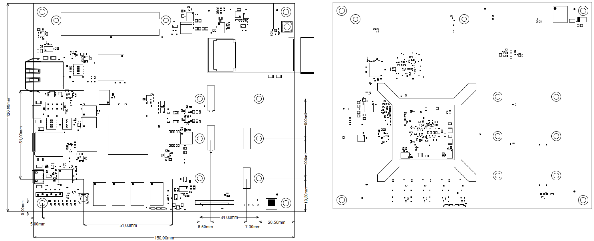
Physical Dimensions
PCB thickness: 1.6 mm.
| Scroll Title |
|---|
| anchor | Figure_TS_PD |
|---|
| title-alignment | center |
|---|
| title | Physical Dimension |
|---|
|
| Scroll Ignore |
|---|
| draw.io Diagram |
|---|
| border | false |
|---|
| |
|---|
| diagramName | Figure_TS_PD |
|---|
| simpleViewer | false |
|---|
| width | |
|---|
| links | auto |
|---|
| tbstyle | top |
|---|
| diagramDisplayName | |
|---|
| lbox | false |
|---|
| diagramWidth | 1006 |
|---|
| revision | 2 |
|---|
|
|
| Scroll Only |
|---|
| scroll-pdf | true |
|---|
| scroll-office | true |
|---|
| scroll-chm | true |
|---|
| scroll-docbook | true |
|---|
| scroll-eclipsehelp | true |
|---|
| scroll-epub | true |
|---|
| scroll-html | true |
|---|
| 
|
|
Currently Offered Variants
| Scroll Title |
|---|
| anchor | Table_VCP_SO |
|---|
| title-alignment | center |
|---|
| title | Trenz Electronic Shop Overview |
|---|
|
| Scroll Table Layout |
|---|
| orientation | portrait |
|---|
| sortDirection | ASC |
|---|
| repeatTableHeaders | default |
|---|
| sortByColumn | 1 |
|---|
| sortEnabled | false |
|---|
| cellHighlighting | true |
|---|
|
|
Revision History
Hardware Revision History
| Scroll Title |
|---|
| anchor | Table_RH_HRH |
|---|
| title-alignment | center |
|---|
| title | Hardware Revision History |
|---|
|
| Scroll Table Layout |
|---|
| orientation | portrait |
|---|
| sortDirection | ASC |
|---|
| repeatTableHeaders | default |
|---|
| sortByColumn | 1 |
|---|
| sortEnabled | false |
|---|
| cellHighlighting | true |
|---|
|
| Date | Revision | Changes | Documentation Link |
|---|
| 2023-02-09 | REV01 | Initial revision | REV01 | | 2023-06-20 | REV02 | Inverted card detect (pullup-> pulldown) Increased number of capacitors on VTT (C388,C389) Added 1K pullup on FAULTn_12V (R5) Added 4-pin connector J17 for FAN and correspoding circuit. PWM and TACHO connected to ARTIX VERSAL JTAG connection corrected Added CRUVI connector description on silkscreen Changed polarity for CSI2-CAM diff pairs Update from library Changed R266 to 12K and added R281 Changed enable 3V3 after 5V0 (R99), Pullup on PG_5V0 connected to 5V0 rail. Replaced C256 (2,2µF) by 2x 1µF - Set R131 and R132 to not fitted (2023-08-18)
| REV02 | | 2024-01-17 | REV03 | 1. Added OSPI compatibility, renamed sheet (QSPI_SD_eMMcC -> SD_eMMcC) and added sheet QSPI_OSPI.
2. Added D12 and pull-up R170 for correct reset levels, set R131 and R132 to assembled
3. Added Pin header J18 for direct JTAG access
4. Moved V_L22 diff. pair to clock capable pins on Atrix
5. Small improvements of MGT routing, added anti-pads, optimized VIAs, increased clearance.
6. Versal changed from Engeniering Sample to production (pre-production for ES9749) chips
7. Replaced U20 by IR3899A DCDC
8. Removed U34 (I2C levelshifter for former U20)
9. Added Common mode chock L29, Fuse F1, C288, C289 and D13 to 12V input rail.
10. Moved PM1, PM2, PM5, PM6
11. Silkscreen dip switch description:
Added boot mode "OSPI" selectable via dip S2C, former connection (User PMC MIO27) moved to S4D.
- added OSPI boot mode,
- S4D is user dip switch connected to Versal PMC (MIO27)
12. Updated all components from lib | REV03 |
|
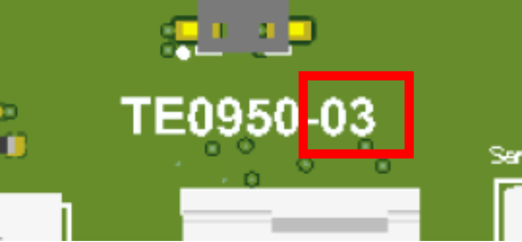
Hardware revision number can be found on the PCB board together with the module model number separated by the dash.
| Scroll Title |
|---|
| anchor | Figure_RV_HRN |
|---|
| title-alignment | center |
|---|
| title | Board hardware revision number. |
|---|
|
| Scroll Ignore |
|---|
| draw.io Diagram |
|---|
| border | false |
|---|
| |
|---|
| diagramName | Figure_RV_HRN |
|---|
| simpleViewer | false |
|---|
| width | |
|---|
| links | auto |
|---|
| tbstyle | top |
|---|
| diagramDisplayName | |
|---|
| lbox | false |
|---|
| diagramWidth | 340 |
|---|
| revision | 2 |
|---|
|
|
| Scroll Only |
|---|
|
|
Document Change History
| Page properties |
|---|
|
- Note this list must be only updated, if the document is online on public doc!
- It's semi automatically, so do following
Add new row below first Copy "Page Information Macro (date)" Macro-Preview, Metadata Version number, Author Name and description to the empty row. Important Revision number must be the same as the Wiki document revision number Update Metadata = "Page Information Macro (current-version)" Preview+1 and add Author and change description. --> this point is will be deleted on newer pdf export template - Metadata is only used of compatibility of older exports
|
| Scroll Title |
|---|
| anchor | Table_RH_DCH |
|---|
| title-alignment | center |
|---|
| title | Document change history. |
|---|
|
| Scroll Table Layout |
|---|
| orientation | portrait |
|---|
| sortDirection | ASC |
|---|
| repeatTableHeaders | default |
|---|
| sortByColumn | 1 |
|---|
| sortEnabled | false |
|---|
| cellHighlighting | true |
|---|
|
| Date | Revision | Contributor | Description |
|---|
| Page info |
|---|
| infoType | Modified date |
|---|
| dateFormat | yyyy-MM-dd |
|---|
| type | Flat |
|---|
|
| | Page info |
|---|
| infoType | Current version |
|---|
| prefix | v. |
|---|
| type | Flat |
|---|
| showVersions | false |
|---|
|
| | Page info |
|---|
| infoType | Modified by |
|---|
| type | Flat |
|---|
| showVersions | false |
|---|
|
| Updated MGTs tested speed for REV03 | | | | Updated to REV03 | | | | Typos corrected | | | | |
|
Disclaimer
| Include Page |
|---|
| IN:Legal Notices |
|---|
| IN:Legal Notices |
|---|
|