Page History
| Page properties | ||||
|---|---|---|---|---|
| ||||
Template Revision 1.1 For carrier - module combination, create main getting started page for carrier Design Name always "TE Series Name" +Getting Started, for example "TE0701 Getting started" and add carrier/module combination in the description → link on the module resource page also For whole board, use the board name, for example "TEBF0911 Getting Started"
|
| Page properties | ||||
|---|---|---|---|---|
| ||||
In this section you must explain how to power on the board and run the Reference Design (test board) on the particular module. The main points must be mentioned are:
|
TEB2000 with TEM0007
Overview
| Scroll Title | |||||||||||||||||||||||||||||||||||||||||||||||
|---|---|---|---|---|---|---|---|---|---|---|---|---|---|---|---|---|---|---|---|---|---|---|---|---|---|---|---|---|---|---|---|---|---|---|---|---|---|---|---|---|---|---|---|---|---|---|---|
| |||||||||||||||||||||||||||||||||||||||||||||||
|
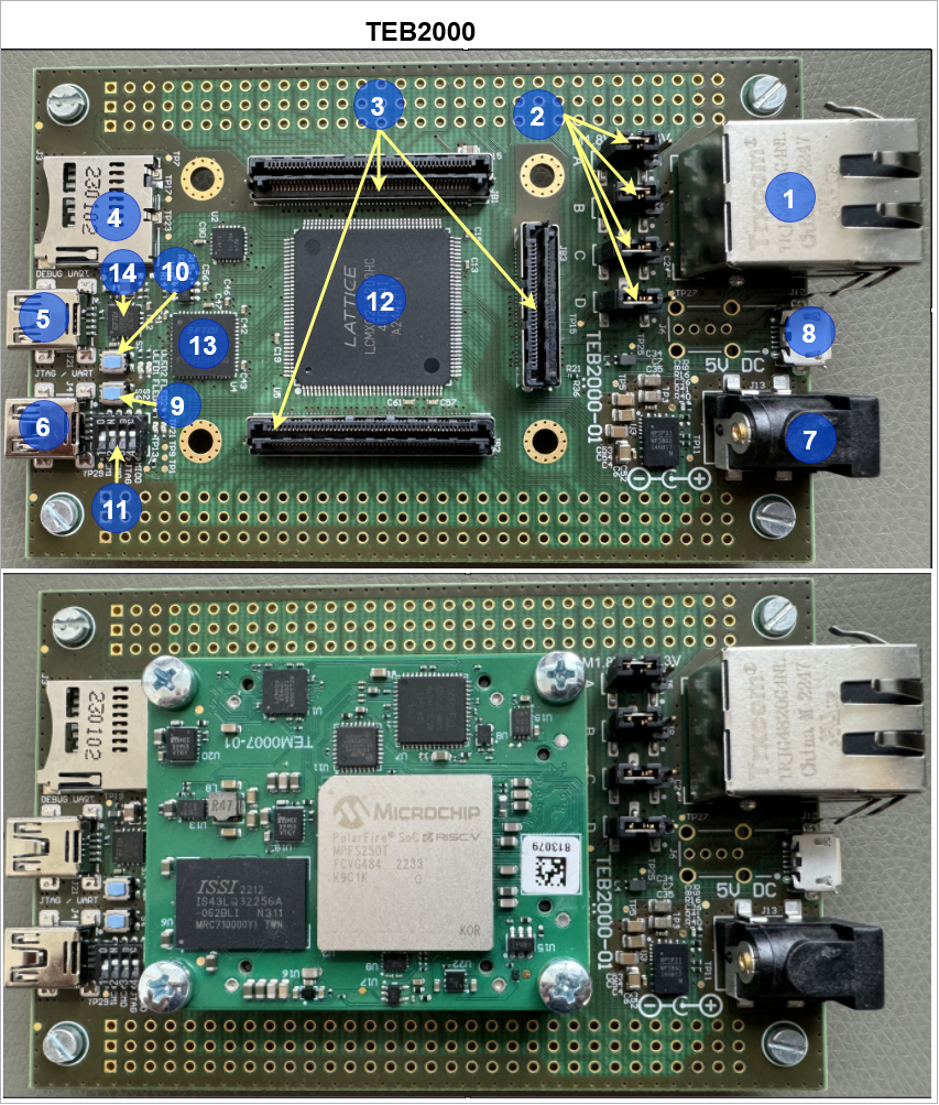
Board Overview
| Number | Note |
|---|---|
| 1 | J14- Ethernet interface |
| 2 | J5,J8,J9,J10- Bank voltage adjustment |
| 3 | JB1,JB2,JB3- B2B connector |
| 4 | J3- SD card socket |
| 5 | J21- UART0 socket |
| 6 | J4- UART1 socket |
| 7 | J13- 5V voltage input |
| 8 | J12- USB stick socket |
| 9 | S6- Reset button (SRST) (Soft reset) |
| 10 | S1- Reset button ( Hard reset) |
| 11 | S2- Dip Switch |
| 12 | U5- CPLD Chip |
| 13 | U4- FTDI chip for UART1 interface (Linux console) |
| 14 | U12- FTDI chip for UART0 interface (HSS console) |
Power supply
| Page properties | ||||
|---|---|---|---|---|
| ||||
The input power supply must be mentioned. |
Single 5V power supply with minimum current capability of 1.5A is recommended to power on the board.
DIP-Switches and Push Buttons
| Page properties | ||||
|---|---|---|---|---|
| ||||
Explain all DIP switches functionality. |
There is two switch reset switchs on the board (S1 and S6) which is connected to RESET signals, these reset the system entirely. The S6 is a soft reset buttom and S1 button (SRST) that is not directed to CPLD chip. The S1 signal is connected to CPLD chip and is used in firmware code to create a reset signal via hardware.
| Scroll Title | |||||||||||||||||||||||||||||||||||||||||||||||||||||||||||
|---|---|---|---|---|---|---|---|---|---|---|---|---|---|---|---|---|---|---|---|---|---|---|---|---|---|---|---|---|---|---|---|---|---|---|---|---|---|---|---|---|---|---|---|---|---|---|---|---|---|---|---|---|---|---|---|---|---|---|---|
| |||||||||||||||||||||||||||||||||||||||||||||||||||||||||||
|
There is no DIPs DIP switch on the TEM0007 module.
Jumpers
| Page properties | ||||
|---|---|---|---|---|
| ||||
Explain all Jumpers functionality and connection. |
| Scroll Title | ||||||||||||||||||||||||||||||||||
|---|---|---|---|---|---|---|---|---|---|---|---|---|---|---|---|---|---|---|---|---|---|---|---|---|---|---|---|---|---|---|---|---|---|---|
| ||||||||||||||||||||||||||||||||||
|
I2C to GPIO
Such signals same as NOSEQ can be read or written via i2c commands in linux console. For more information about it refer to TEB2000 CPLD#I2C to GPIO
LEDs
| Page properties | ||||
|---|---|---|---|---|
| ||||
Explain all user LEDs functionality and connections. |
There are six LEDs which can be used for variant purposes.
| Scroll Title | ||||||||||||||||||||||||||||||||||||||||||||||||||||||||||||||||||||||||||||||
|---|---|---|---|---|---|---|---|---|---|---|---|---|---|---|---|---|---|---|---|---|---|---|---|---|---|---|---|---|---|---|---|---|---|---|---|---|---|---|---|---|---|---|---|---|---|---|---|---|---|---|---|---|---|---|---|---|---|---|---|---|---|---|---|---|---|---|---|---|---|---|---|---|---|---|---|---|---|---|
| ||||||||||||||||||||||||||||||||||||||||||||||||||||||||||||||||||||||||||||||
* This LEDs exit on the ethernet socket (J14A). |
Note: The TEM0007 module has no LED.
JTAG/UART
| Page properties | ||||
|---|---|---|---|---|
| ||||
Explain JTAG or UART connection breifly. |
JTAG and UART connections are available through micro USB connector. MIO14 is driven by BDBUS0 (FTDI RX). BDBUS1 (FTDI TX) is driven by MIO15 . MIO13 is driven by UART_TXD. UART_RXD is driven by MIO12.
| Scroll Title | ||||||||||||||||||||||||||||||||||||||||||||||||||||||||||||||||||||||||||||||||||||
|---|---|---|---|---|---|---|---|---|---|---|---|---|---|---|---|---|---|---|---|---|---|---|---|---|---|---|---|---|---|---|---|---|---|---|---|---|---|---|---|---|---|---|---|---|---|---|---|---|---|---|---|---|---|---|---|---|---|---|---|---|---|---|---|---|---|---|---|---|---|---|---|---|---|---|---|---|---|---|---|---|---|---|---|---|
| ||||||||||||||||||||||||||||||||||||||||||||||||||||||||||||||||||||||||||||||||||||
| ||||||||||||||||||||||||||||||||||||||||||||||||||||||||||||||||||||||||||||||||||||
For more information refer to TEB2000 CPLD#UART
Reference Designs
| Page properties | ||||
|---|---|---|---|---|
| ||||
In this Section you must refer to the Reference Design (Test board) for the particular module. For Example: TE0728 Reference Designs |
Notes
| Page properties | ||||
|---|---|---|---|---|
| ||||
In this Section you must refer to the Resources Page for the particular module. For Example: TE0728 Resources |
| Scroll Only | ||
|---|---|---|
|
| Scroll pdf ignore | ||||||
|---|---|---|---|---|---|---|
|
Overview
Content Tools