Page History
| Scroll Ignore |
|---|
Download PDF version of this document. |
| Scroll pdf ignore | |
|---|---|
Table of Contents
|
Overview
| Scroll Only (inline) |
|---|
Refer to "https://shop.trenz-electronic.de/de/Download/?path=Trenz_Electronic/TE0722/REV02/Documents" for downloadable version of this manual and additional technical documentation of the product.
|
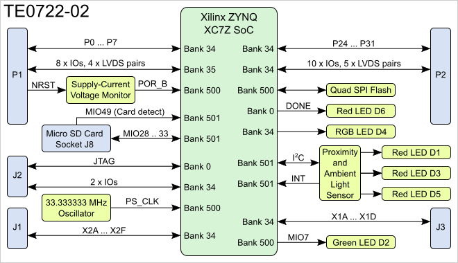
The Trenz Electronic TE0722-02 is a DIPFORTy1 "Soft Propeller" based on the Xilinx ZYNQ-7000 SoC.
Block Diagram
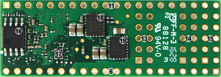
Main Components
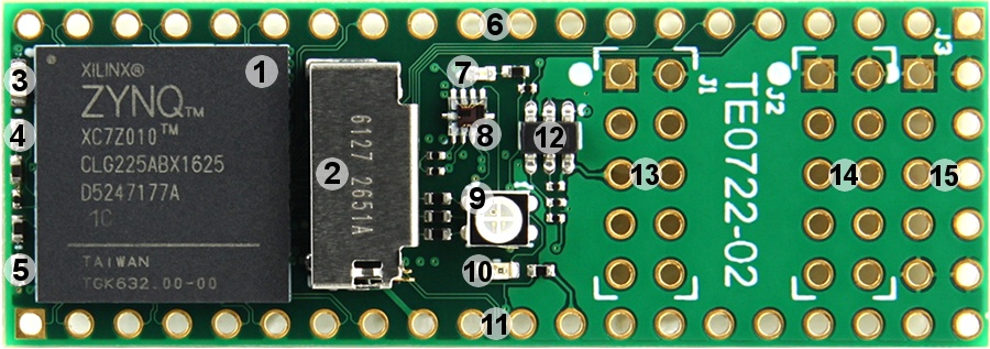
- Xilinx ZYNQ XC7Z010 SoC, U1
- Micro SD card socket with card detect, J8
- Red LED, D3
- Green LED, D2
- Red LED, D6
- 20-pin connector placeholder, P1
- Red LED, D5
- Proximity/ambient light sensor, U4
- RGB LED, D4
- Red LED, D1
- 20-pin connector placeholder, P2
- Ultra-low supply-current voltage monitor, U4
- 2 x 5-pin connector placeholder, J1
- 2 x 5-pin connector placeholder, J2
- 2 x 5-pin connector placeholder, J3
- 16 MByte QSPI Flash memory, U5
- Low power programmable oscillator @ 33.333333 MHz, U8
- 1A PowerSoC DC-DC converter (1.0V), U2
- 1A PowerSoC DC-DC converter (1.8V), U3
Key Features
- Xilinx ZYNQ XC7Z010 SoC
- 16 MByte QSPI Flash
- Dual core ARM A9+
- Micro SD Card socket with card detect signal
- DIP40 form factor (size 18 x 51 mm)
- 34 I/Os on DIP40 header pins
- System status LED (DONE)
- RGB LED connected to PL I/O
- Green user LED connected to ARM CPU GPIO
- Proximity and ambient light sensor
Additional assembly options are available for cost or performance optimization upon request.
Initial Delivery State
Storage device name | Content | Notes |
|---|---|---|
QSPI Flash | Empty |
Signals, Interfaces and Pins
I2C Interface
On-board I2C interface is provided via ZYNQ SoC PS bank 501 pins MIO36 (SCL) and MIO37 (SDA). I2C addresses for on-board devices are listed in the table below:
| I2C Device | I2C Address | Notes |
|---|---|---|
| Si1143-A11-GMR | 0x5A |
JTAG Interface
JTAG access to the Xilinx ZYNQ XC7Z010 SoC is provided through J2 connector.
JTAG Signal | J2 Connector Pin |
|---|---|
| TCK | 4 |
| TDI | 9 |
| TDO | 10 |
| TMS | 8 |
Technical Specifications
Absolute Maximum Ratings
Parameter | Min | Max | Units | Reference Document |
|---|---|---|---|---|
VIN supply voltage | V | - | ||
Storage temperature | -40 | +85 | °C | - |
Recommended Operating Conditions
| Parameter | Min | Max | Units | Reference Document |
|---|---|---|---|---|
| VIN supply voltage | V |
| Note |
|---|
| Assembly variants for higher storage temperature range are available on request. |
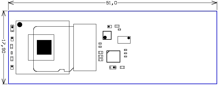
Physical Dimensions
Module size: 18 mm × 51 mm. Please download the assembly diagram for exact numbers.
PCB thickness: 1.6 mm.
Highest part on PCB: approx. 4 mm. Please download the step model for exact numbers.
All dimensions are given in millimeters.
Operating Temperature Ranges
Commercial grade: 0°C to +70°C.
Industrial grade: -40°C to +85°C.
Operating temperature range depends also on customer design and cooling solution. Please contact us for options.
Weight
... g - Plain module
... g - Set of bolts and nuts
Revision History
Hardware Revision History
| Date | Revision | Notes | PCN | Documentation Link |
|---|---|---|---|---|
| 2015-10-23 | 02 | |||
01 |
|
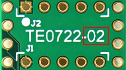
Hardware revision number is printed on the PCB board together with the module model number separated by the dash.
Document Change History
Date | Revision | Contributors | Description |
|---|---|---|---|
| 2017-02-09 | Jan Kumann | Initial document. |
Disclaimer
| Include Page | ||||
|---|---|---|---|---|
|
Overview
Content Tools