Page History
...
| Term | Description |
|---|---|
| Adapter Board | Adapts the Reference Motor to the EDPS Board. |
| Control Board | An electronic board for controlling the EDPS Board; the EDDP Kit uses Digilent , a Digilent board Arty Z7 for that purpose. |
| EDDP | Electronic Drive Development Platform. |
| EDDP Kit | A kit consisting of the EDPS Board, the Reference Motor, the Adapter board and. |
| EDPS Board | An Electric Drive Power Stage Board, the EDDP Kit contains a Trenz Electronic GmbH board TEC0053 to be used as an EDPS Board. |
| Host PC | A computer capable of running a web browser in order to run the Web UI. |
| Reference Motor | The motor included in the EDDP Kit. This motor is of brushless type and is already mated with an encoder. |
| Web UI | A user interface in the form of a web page permitting operating the EDDP. |
...
The Adapter Board is mounted to the EDPS Board using 5 x M6 screws (Labels 0V, A, B, C, 12V on Adapter Board) and with M3 screws and spacer - marked 12V at the left. This Adapter board Board "forwards" (the yellow arrow) the EDPS Board pre-driver supply (12V) to the DC Link main terminal on the EDPS board, so that separate DC Link power supply is not needed allowing easy evaluation of the complete system.
...
Note terminal marked+DC must be left open when using the Adapter boardBoard!
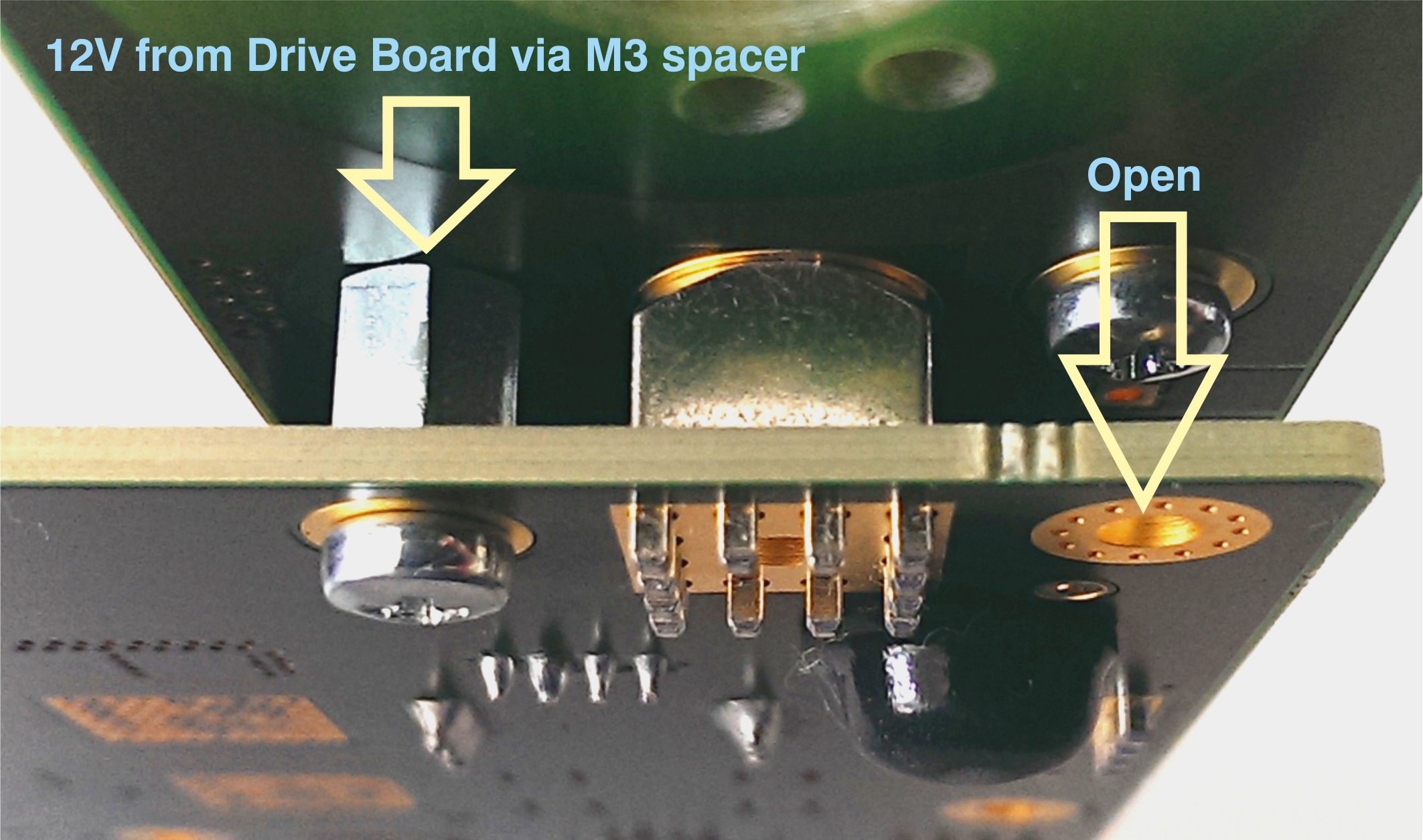
Figure 2: M3 spacer and two M3 screws connect 12V from the EDPS board to the Adapter boardBoard.
Motor Connection
In the EDDP Kit the Reference Motor stator wires for all three phases are already connected to the Adapter Board. Instructions for manual assembly below:
...
Figure 4: Pmod cable alignment to Encoder connectorthe Encoder connector.
Notice that there are 5 pins in the Encoder header while the PMoD female connector has 6 terminals. Red Arrow marks the "empty" terminal at the PMoD Cable.
...
Pin 1 markings are indicated with the arrows, on the Drive EDPS Board a white dot marks 6-pin Pmod header pin 1. This pin should be aligned to the Encoder Pin marked "G" and "1" visible when looking from the bottom up. Please note that Encoder header has 5 terminals while the driver board and Pmod cable have 6 terminals.
Network configuration on the Host PC (Optional)
An overview of network configuration and some methods for network troubleshooting are given.
It is assumed that the operating system on the Host PC is Microsoft Windows 7 or newer. For other operating systems, the basic network principles are the same, but the means of configuration are different; consult the corresponding user guides.
...
Locate the network connection that is to be used for communication with the Control Board and click on it. The network connection status dialog appears (Figure 7).
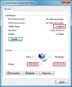
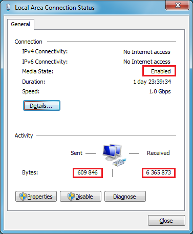
Figure 7: A network connection status dialog, with the media status and number of bytes sent and received highlighted.
...
During normal operation, the number of bytes sent ja received sent and received should increase when there is network traffic - , for example, when pinging the Control Board, when operating the Web UI, when pinging, etc.
...
In the network connection status dialog (Figure 7), click "Details". A Network Connection Details dialog appears:
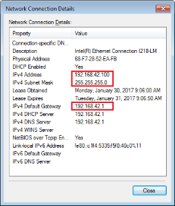
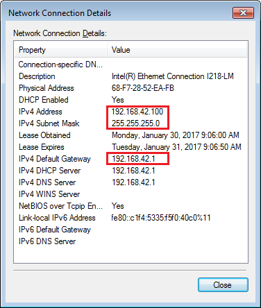
Figure 8: A Network Connection Details dialog, with the important IP settings highlighted.
...
On the network connection status dialog (Figure 7), click "Properties". The following dialog (Figure 9) appears:

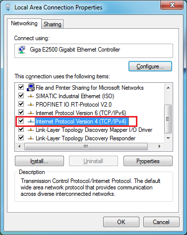
Figure 9: A network connection properties dialog. The item "Internet Protocol Version 4 (TCP/IPv4)" is selected and highlighted.
In the list of items used, select "Internet Protocol Version 4 (TCP/IPv4)" and click "Properties". The following dialog appears:
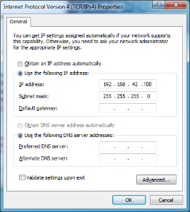
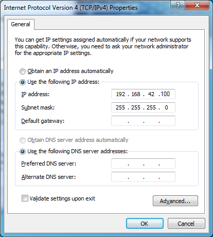
Figure 10: A TCP/IPv4 Properties dialog.
...
A 3-phase permanent-magnet synchronous motor with attached encoder and mechanical load is mounted to a EDPS Board by using an Adapter Board. The EDPS Board is connected to a Control Board ARTY-Z7 through PMOD connectors. A Host PC running a Web Browser connects to the Control Board through a Network.
...
Figure 15: Block diagram of the EDDP.
List of additional documents
| Page break |
|---|
FPGA resources utilization
An excerpt of the FPGA resource utilization by the FOC SDSoC Application Project is shown The additional documents, listed in the Table 2, can be downloaded from Trenz EDDP Web Hub:
. The FPGA used on the Controller Board is Xilinx 7z010clg400-1.
The power draw of the design is about 220mW as measured by the increase of the power draw of the Control Board after configuring the FPGA.
| Type | Used | Available | Util% |
|---|---|---|---|
| Slice LUTs | 5758 | 17600 | 32.72 |
| Slice Registers | 7277 | 35200 | 20.67 |
| F7 Muxes | 33 | 8800 | 0.38 |
| RAMB36/FIFO | 21 | 60 | 35 |
| RAMB18 | 4 | 120 | 3.33 |
| DSP48E1 | 34 | 80 | 42.50 |
| BUFGCTRL | 4 | 32 | 12.50 |
| MMCME2_ADV | 1 | 2 | 50 |
Table 2: FPGA resources utilization.
List of additional documents
The additional documents, listed in the Table 3, can be downloaded from Trenz EDDP Web Hub:
| Title | Description |
|---|---|
| FOC SDSoC | Implementation of a Field-Oriented Control algorithm in C++ with Vivado SDSoC |
| SDSoC Hardware Platform ARTY-Z7 | A basis for building Vivado SDSoC applications running on an Arty-Z7 board connected to a TEC0053 board |
| AXI4-Stream AD7403 | An IP core for filtering the delta-sigma bitstream read from one or more ADC-s of type of AD7403 to an AXI4-Stream of samples |
| AXI4-Stream Encoder | An IP core for converting impulses from a relative index encoder with an index signal to an AXI4-Stream of position and speed data |
| AXI4-Stream PWM | An IP core for generating PWM signals according to the input AXI4-Stream |
| AXI4-Stream Concat | An IP core for concatenating AXI4-Streams |
| Web GUI | A Web UI to control and monitor an EDPS Board over the Network API |
| Network API | A communication protocol, based on Websockets, to control an EDPS board |
| Embedded Linux Code | A server program interfacing to an EDPS board and implementing the Network API and the functions of a Web Server |
Table 23: List of additional documents.
...
Date | Revision | Contributors | Description | ||||||||
|---|---|---|---|---|---|---|---|---|---|---|---|
| Jan Kumann | General formatting changes and small corrections. | |||||||||
2017-08-14 | v.10 | Antti Lukats, Andrei Errapart | Initial document. |
Table 24: Document change history.
...
Overview
Content Tools