...
- Pin 1(DQ), 3 (GND),5 (+3.3V) at the same 1-wire bus as the onboard one
- Pin 2(DQ), 4 (GND),6 (+3.3V) at a separate 1-wire bus
Power and Power-On Sequence
...
+ DC 5...48V Optional Motor Supply
SAFETY INSTRUCTIONS:
| Risk | Counter Measure | Comment | |
|---|
| Short Circuit at High Current Connections | - The Eval Board must be used on a non conducting surface!
- The Eval Boad High Current Signals conducting up to 30A nominal (Motor outputs A, B, C and FUSE F1 Connectors J5 an J6, and internal connections), must be covered by isolating mechanically stable material, highly recommended is to use the delivered "Isolating cover PCB" which needs to be mounted to the mounting holes H1, H9, H3, H4 with the deliverd 10mm isolating spacers.
The High Current potentials are shown white marked:
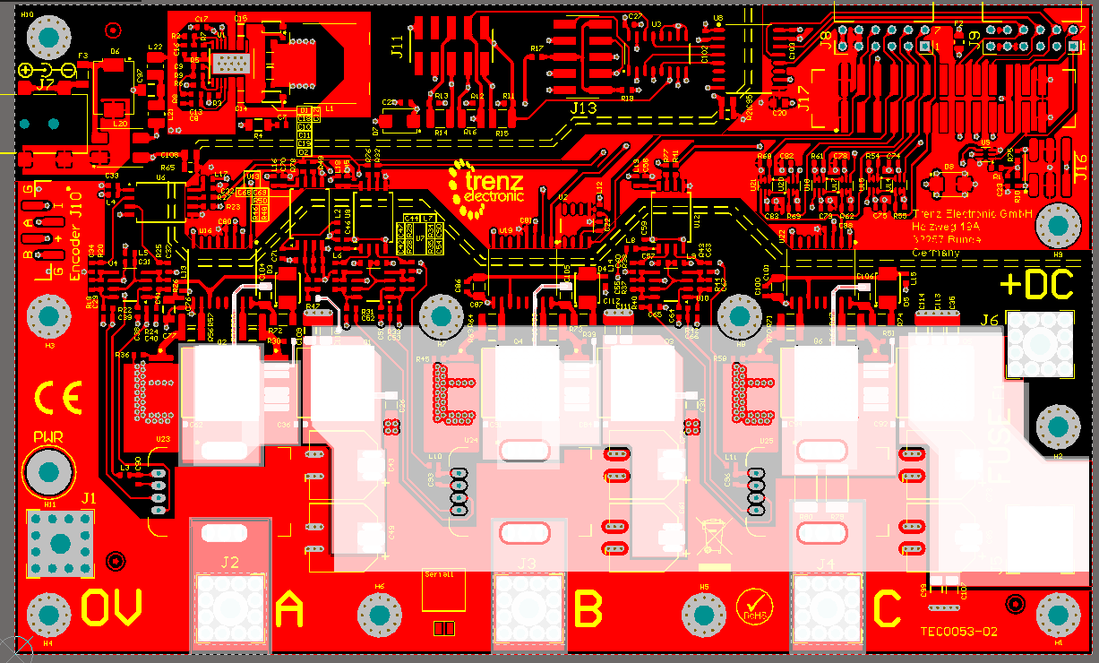 Image Added Image Added
The mounted "Isolating cover PCB" is marked green:
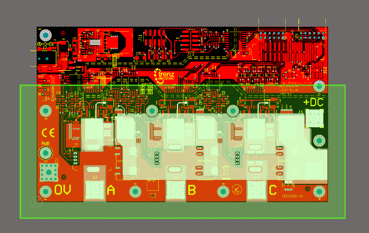 Image Added Image Added
The used cable lugs need to be isolated in the area outstanding the outer border of the Eval Board, to make sure that the Isolating Cover PCB is overlapping the conducting material by minimum of 2 cm.
| | |
| | | | |
| | | | |
This motor supply is only usable after the following steps are done:
...