Page History
| Table of Contents |
|---|
Text changed after safety review for temporary marking in blue.
Overview
Option 1: with DC +12V Reference Motor Board (Delivery condition)
...
- This Eval Board comes with the already mounted and wired "Reference Motor Board"
- One "Arty Z7" Board: http://store.digilentinc.com/arty-z7-apsoc-zynq-7000-development-board-for-makers-and-hobbyists/usable with the reference FPGA IPs: TODO insert link
- Any DC +12V must be supplied to both boards supply connectors
(Two AC/DC Wall Mount Adapters are delivered as optional DC +12V power source) - One FUSE F1 30A for motor supply option 2
Signals, Interfaces and Pins
Controller Board Connections (Arty etc.)
General Safety Instructions
- There is a possible risk of burns due to hot surfaces while running the Board. This e.g. might be caused by an overcurrent at the motor outputs.
- The product is only allowed to be used in horizontal position on a non conducting and non inflameable surface.
- All externaly connected power sources must be SELV protected (Separated or safety extra-low voltage).
- This product is only allowed to be used in dry an indoor environment.
- This product is not allowed to be used unattended by an electrical specialist.
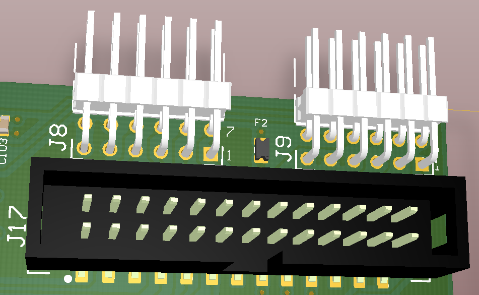
Signals, Interfaces and Pins
Controller Board Connections (Arty etc.)
| Signalnames | Connector J8 | Connector J9 | Connector J17 |
|---|---|---|---|
Digital Supply to EDPS | Pin 6, 12: +3.3V | Pin 6, 12: +3.3V Pin 5, 11: GND | Pin 5, 6, 21, 22: +3.3V Pin 1, 2, 25, 26: GND |
Motor Driver PWM Signals to EDPS High and Low Side control signals
| Pin 1: G1H - Ch.A HighSide | Pin 11: G1H - Ch.A HighSide | |
| ADC Clock Signal to EDPS | Pin 1: SCLK | Pin 23: SCLK | |
| Encoder Digital Signals from EDPS | Pin 8: ENC_A | Pin 20: ENC_A | |
| Motor Current ADC "raw" Signals from EDPS (usable with FPGA IP) | Pin 2: SDI1 - Current Ch.A | Pin 19: SDI1 - Current Ch.A | |
| Supply Voltage ADC "raw" Signal from EDPS (usable with FPGA IP) | Pin 7: SDIV - from DC_LINK | Pin 24: SDIV - from DC_LINK | |
| 1-Wire bus for temperature measurement | Pin 10: EXT1 - 1-Wire Bus 1 Pin 4: EXT2 - 1-Wire Bus 2 | Pin 4: EXT1 - 1-Wire Bus 1 | |
| Not connected pins | none | none | Pin 13, 14 |
...
Power and Power-On Sequence
Power Supply
+ DC 12V Motor Driver and Motor SupplyMotor Driver and Motor Supply
This externaly supplies power sources must be SELV protected (Separated or safety extra-low voltage).
The motor drivers and the reference motor on the pre-mounted motor board TEC0060 are supplied by this voltage.
...
+ DC 5...48V Optional Motor Supply
SAFETY INSTRUCTIONS:
This option is
SAFETY INSTRUCTIONS:
This externaly supplies power sources must be SELV protected (Separated or safety extra-low voltage).
This option is
only usable at your own risk- only allowed to be used for electrical specialist for the used electical voltage and power conditions
- only allowed to be used under electrical laboratory conditions
- only allowed to be used in horizontal position on a non conducting and non-inflammable surfaceonly usable at your own risk
- only allowed to be used for electrical specialist for the used electical voltage and power conditionswith a wiring, which fullfills the current rating for the maximum possible currents.
- The maximung current might be limited by the used fuse between connector J5 and J6 or e.g. by the limit of an connected external power source.
- only allowed to be used under electrical laboritory conditionsused with a suitalble connector.
only allowed to be used in horizontal position on a non conducting surface- For the power contacts with M5 screw connections a M5 cable lug must be used.
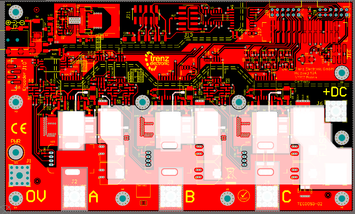
- only allowed to be used, if the "Eval Boad high current signals" conducting up to 30A nominal, are covered by isolating, mechanically stable material
The "Eval Boad high current signals" are the motor outputs A, B, C and Fuse F1 Connectors J5 an J6 and further internal connections shown white marked in the following picture:
- Highly recommended is to use the delivered "Isolating cover PCB" (marked in green), which needs to be mounted to the mounting holes H1, H9, H3, H4 with the deliverd 10mm isolating spacers:
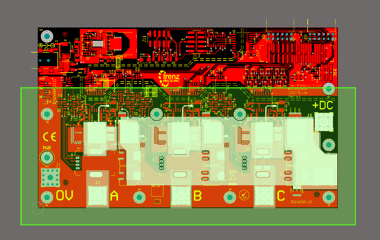
- The used cable lugs need to be isolated in the area outstanding the outer border of the Eval Board.
Intention is to make sure that the "Isolating Cover PCB" is overlapping the conducting material by a minimum of 2 cm.
...
Overview
Content Tools