Page History
...
- There is a possible risk of burns due to hot surfaces while running the Board. This e.g. might be caused by an overcurrent at the motor outputs.
- The product is only allowed to be used in horizontal position on a non conducting and non inflameable surface.
- All externaly connected power sources must be SELV protected (Separated or safety extra-low voltage).
- This product is only allowed to be used in dry an indoor environment.
- This product is not allowed to be used unattended by an electrical specialist.
- During operations it is not allowed to change the wiring or mechanical setup.
- For set up the wiring switch off or disconnect all external power suplies.
Signals, Interfaces and Pins
...
only usable at your own risk- only allowed to be used for electrical specialist for the used electical voltage and power conditions
- only allowed to be used under electrical laboratory conditions
- only allowed to be used in horizontal position on a non conducting and non-inflammable surface
- only allowed to be used with a wiring, which fullfills the current rating for the maximum possible currents.
- The maximung current might be limited by the used fuse between connector J5 and J6 or e.g. by the limit of an connected external power source.
- only allowed to be used with a suitalble connector.
For the power contacts with M5 screw connections a M5 cable lug must be usedappropriate connectors at the M5 screw connectors, which means M5 cable lugs must be used and fastend accorting to technical standards. - only allowed to be used, if the "Eval Boad high current signals" conducting up to 30A nominal, are covered by isolating, mechanically stable material
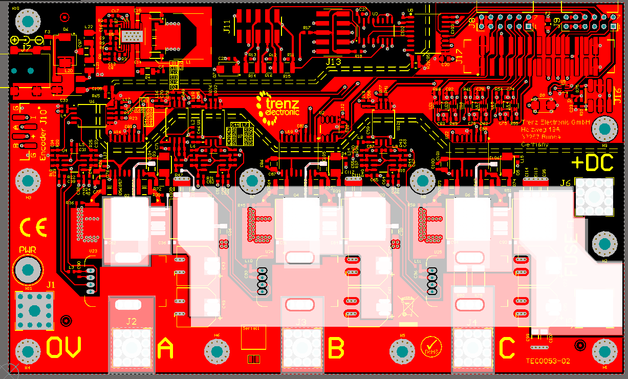
The "Eval Boad high current signals" are the motor outputs A, B, C and Fuse F1 Connectors J5 an J6 and further internal connections shown white marked in the following picture:
- Highly recommended is to use the delivered "Isolating cover PCB" (marked in green), which needs to be mounted to the mounting holes H1, H9, H3, H4 with the deliverd 10mm isolating spacers:
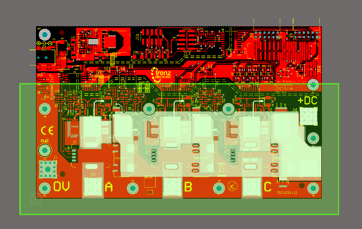
- The used cable lugs need to be isolated in the area outstanding the outer border of the Eval Board.
Intention is to make sure that the "Isolating Cover PCB" is overlapping the conducting material by a minimum of 2 cm.
...
Overview
Content Tools