Page History
...
Following table contains the assignment of the MIO pins to the configured interfaces:
| MIO | Configured as | Alternate | Notes |
|---|---|---|---|
| 0..12 | Dual QSPI | - | Dual Flash Memory on TE0808 SoM; Bootable |
| 13..23 | SD0: eMMC | - | eMMC Memory U2; Bootable |
| 24, 25 | - | CPLD (U39) MUXED | - |
| 26..29 | PJTAG0 | CPLD (U17 MUXED | Bootable JTAG |
| 30 | - | CPLD (U39) MUXED | - |
| 31 | PCIe | CPLD (U39) MUXED | Same as ZCU102 |
| 32 | - | CPLD (U39) MUXED | - |
| 33 | PMU | CPLD (U39) MUXED | Same as ZCU102 |
| 34..37 | DisplayPort Aux | CPLD (U39) MUXED | - |
| 38, 39 | I2C0 | - | - |
| 40, 41 | CAN1 | CPLD (U39) MUXED | - |
| 42, 43 | UART0 | CPLD (U39) MUXED | - |
| 44 | I2C Interrupt | CPLD (U39) MUXED | - |
| 45..51 | SD1: SD | - | Bootable MikeoSD / MMC Card |
| 52..63 | USB0 | - | - |
| 64..75 | GEM3 | - | Ethernet RGMII |
| 76, 77 | MDC / MDIO | - | Ethernet RGMII |
Table 5: MIO Assignment
On the carrier board there are up to 4 USB3.0 Super Speed ports available, which are also downward compatible to USB2.0 High Speed ports. The USB3.0 ports are provided by the IC U4, Cypress Semiconductor CYUSB3324 4-port USB3.0 Hub. The pin-strap configuration option of the USB3.0 Hub U4 is disabled, so the Hub will only be configurable over the configuration EEPROM U5. The I²C interface of the EEPROM is also accessible by the MPSoC through I²C switch U16.
...
- SATA (PS GT bank 505, MGT2 Lane)
- Display-Port (PS GT bank 505, MGT3 Lane, only TX-pair routed)
- PCI Express (PS GT bank 505, MGT0 Lane)
| Function | MGT Lane | Ref Clock | Clock Source | Comment |
|---|---|---|---|---|
| PCIe | PS 0 | 100 MHz | Si5345 (CLK0 of prog. PLL on mounted SoM) | - |
| USB3 | PS 1 | 100 MHz | Optional Oscillator U6 | - |
| SATA | PS 2 | 150 MHz | Oscillator U23 | - |
| DP.0 | PS 3 | 27 MHz | - | Display Port |
Table 6: PS GT Lane Assignment
...
The TEBF0808 carrier board provides the high speed MGT interface connectors "SFP+" (Enhanced small form-factor pluggable) and Samtec "FireFly". Each of this connectors are capable of data transmission rates up to 10 Gbit/s.
| Function | MGT Lane | Ref Clock | Clock Source | Comment |
|---|---|---|---|---|
| FireFly | B128 MGT Lanes 0..3 | - | - | - |
| SFP | B230 MGT Lane 2 | 125/156.25 MHz | Si5345 (CLK7 of prog. PLL on mounted SoM) | - |
| SFP | B230 MGT Lane 3 | 125/156.25 MHz | Si5345 (CLK7 of prog. PLL on mounted SoM) | - |
Table 6: MGT Lane Assignment
...
Additionally the carrier board provides PMOD connectors with GPIO and I²C interface. Following table
| PMOD | Interface | Connected with | Notes |
|---|---|---|---|
| P1 | GPIO | HP Bank 65 of MPSoC (4 I/O's) System Controller CPLD U17 (I/O's) | Voltage translation via IC U33 with direction control, only singled-ended signaling possible |
| P2 | I²C | 8-channel I²C Switch U27 | Accessible on MPSoC's I²C interface |
| P3 | I²C | 8-channel I²C Switch U27 | Accessible on MPSoC's I²C interface |
Table 7: PMOD Pin Assignment
...
- Reset Button
- Power Button
- Power LED
- Hard Disc (HD) LED
- Intel High Definition Audio (HDA) Jacks
| Header |
|---|
| Pin Name | Function | Connected to |
|---|
| Notes | |
|---|---|
| J10 | Pin 1, HD LED+ |
HD LED Anode |
Supply | SC CPLD U39 | also connected to switch button S1 also connected to switch button S2 |
| J9 | Pin 1, PORT1L |
Pin 2, GND | Microphone Jack Left Microphone Jack Right Audio Out Jack Left Audio Out Jack Right Jack Detect / Mic in Ground | 24-bit Audio Codec IC U3 | - |
| J23 | Pin 1, 3V3SB Pin 4, S1 |
| 3.3V DC Supply PC compatible Beeper | SC CPLD U39 | - | ||
| J26 | Pin 1, GND | Ground 12V DC Supply RPM PWM | SC CPLD U39 | 4-wire PWM FAN connector |
| J35 | Pin 1, GND | Ground 12V DC Supply RPM PWM | SC CPLD U39 | 4-wire PWM FAN connector |
| J19 |
Pin 1, GND | Ground 5V DC Supply |
| Load Switch Q3 (5V DCDC) | 2-wire FAN connector Fan off/on switchable by signal 'FAN_FMC_EN' on SC CPLD U39 |
Table 8: PC compatible Headers
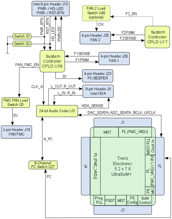
Figure 7: TEBF0808 PC Compatible Headers
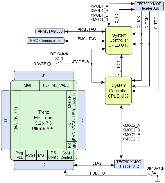
JTAG Interface
The TEBF0808 carrier board provides several JTAG interfaces to program both the System Controller CPLDs and the Zynq Ultrascale+ MPSoC.
Therefore, the board is equipped with two JTAG/UART headers, which have 'XMOD-FT2232H FTDI JTAG Adapter'-compatible pin-assignment
Overview
Content Tools