Page History
...
- Xilinx SDSoC 2017.1 for SDSoC Design Flow or
- Xilinx Vivado 2017.1 for HLS Design Flow
- PC that satisfies the host workstation requirements for Xilinx Tools
- Controller Board (Default: Digilent ARTY-Z 7010)
- Micro-USB Cable (not included in the EDDP kit)
- RJ45 ethernet Cable (not included in the EDDP kit)
- 12V Wall supply for Controller board (included in EDDP kit)
- microSD Card (included in the EDDP kit)
- EDPS Drive Board TEC0053 (Default: 2 phase measurement, max 25A)
- EDPS Motor Adapter Board TEC0060 with default Motor/Encoder installed and 12V Wall supply or
- Custom Motor and Encoder with cables and DC Link power source
- Experience with Xilinx SDSoC and/or Xilinx Vivado. Pre-requisites: basic knowledge of Xilinx All Programmable FPGA and/or SoC devices, basic knowledge of Xilinx SDK and C/C++ programming
Installation
todo
SDSoC based FOC Implementation
Vivado HLS based FOC Implementation
EDDP System - TODO
Hardware - TODO
Software - TODO
Motor - TODO
Block Diagram - TODO
Functional description - TODO
Control Board
Digilent ARTY-Z 7010 is considerd as primary and default Control Board for EDDP as it is delivered as part of the EDDP Kit. In all cases the documentation for the Control Board is not considered part of this manual. All technical data and user guides and manuals for the Controller Board are provided by the controller board manufacturer. This manual describes only information relevent to the actual use of ARTY-Z as Control Board within the scope of EDDP.
EDPS
...
Board TEC0053
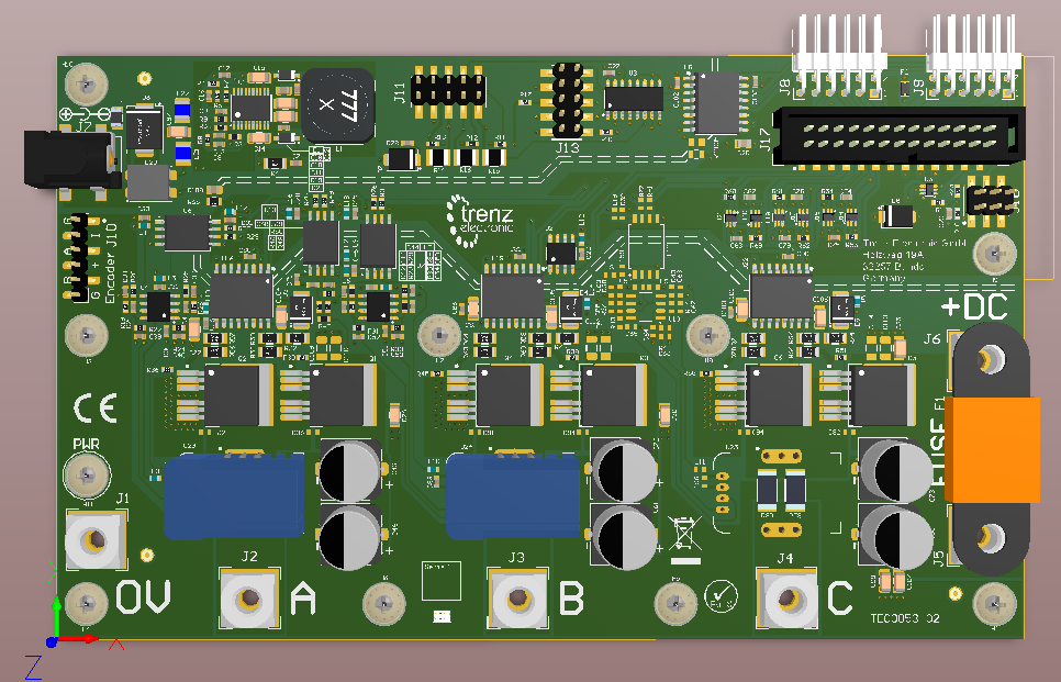
Key Features
- Motor Evaluation with a FPGA controller board, recommended with the Digilent Arty Z7 board
- Quick evaluation with reference motor board
- Power option up to 48V and 30A main supply current
Block Diagram
...
- MOSFET drivers for 3-phase BLDC Motors
- Current measurement for 2-phases (3 phase measurement optional)
- Temperature sensor on board and 1-Wire bus external option
- Encoder input (differential or single ended signals)
Key Features
- Motor Evaluation with a FPGA controller board, recommended with the Digilent Arty Z7 board
- Quick evaluation with reference motor board
- Power option up to 48V and 30A main supply current
...
- differential or single ended signals)
Scope of Delivery
- This Eval Board comes with the already mounted and wired "Reference Motor Board"
- One "Arty Z7" Board: http://store.digilentinc.com/arty-z7-apsoc-zynq-7000-development-board-for-makers-and-hobbyists/usable with the reference FPGA IPs: TODO insert link
- Any DC +12V must be supplied to both boards supply connectors
(Two AC/DC Wall Mount Adapters are delivered as optional DC +12V power source) - One FUSE F1 30A for motor supply option 2
...
Signals, Interfaces and Pins
Control Board Connections
...
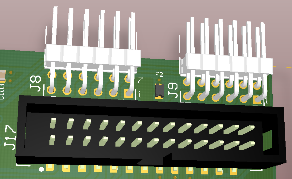
| Signalnames | Connector J8 | Connector J9 | Connector J17 |
|---|---|---|---|
Digital Supply to EDPS | Pin 6, 12: +3.3V | Pin 6, 12: +3.3V Pin 5, 11: GND | Pin 5, 6, 21, 22: +3.3V Pin 1, 2, 25, 26: GND |
Motor Driver PWM Signals to EDPS High and Low Side control signals
| Pin 1: G1H - Ch.A HighSide | Pin 11: G1H - Ch.A HighSide | |
| ADC Clock Signal to EDPS | Pin 1: SCLK | Pin 23: SCLK | |
| Encoder Digital Signals from EDPS | Pin 8: ENC_A | Pin 20: ENC_A | |
| Motor Current ADC "raw" Signals from EDPS (usable with FPGA IP) | Pin 2: SDI1 - Current Ch.A | Pin 19: SDI1 - Current Ch.A | |
| Supply Voltage ADC "raw" Signal from EDPS (usable with FPGA IP) | Pin 7: SDIV - from DC_LINK | Pin 24: SDIV - from DC_LINK | |
| 1-Wire bus for temperature measurement | Pin 10: EXT1 - 1-Wire Bus 1 Pin 4: EXT2 - 1-Wire Bus 2 | Pin 4: EXT1 - 1-Wire Bus 1 | |
| Not connected pins | none | none | Pin 13, 14 |
...
- +3V3 Supply from the FPGA Board, generated by FPGA Board supply
- +12V and
- optional +5..48V Motor Supply
Variants Currently In Production (better remove this)
TODO:
...
Reference Motor Board TEC0060
For easy connection of the reference Motor and Encoder to the Driver board a special Motor Adapter Board TEC0060 is included in the EDDP Kit.
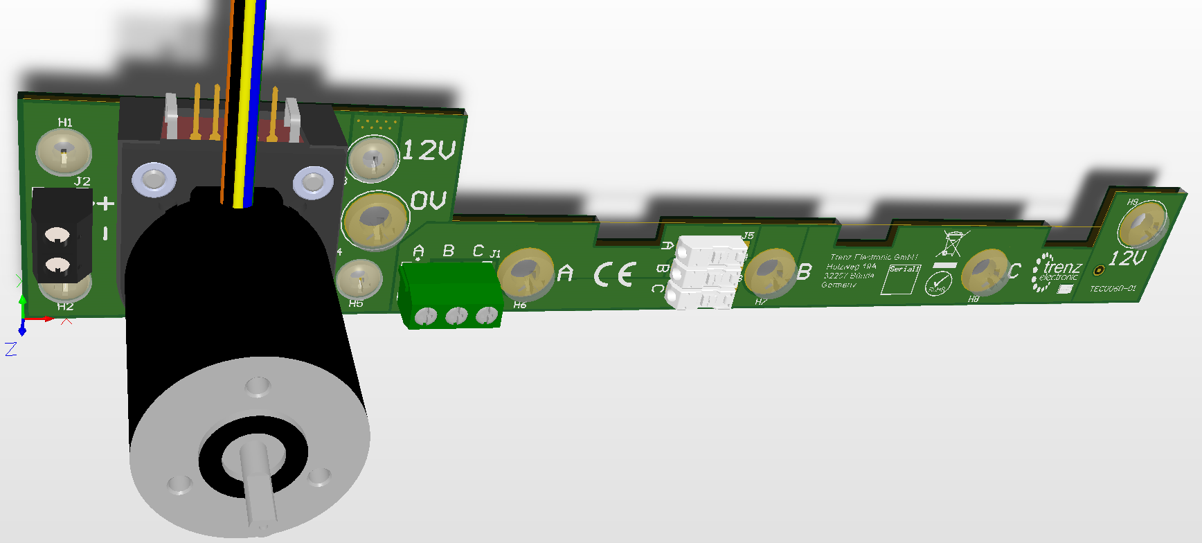
Reference Motor
...
The manufaturer of the reference motor is Anaheim Automation and the order code of the delivered combination of the motor with encoder is BLWR111D-24V-10000-1000SI. Please note that the encoder is not available separatly, they are premounted to the motor at the manufacturer.
The nominal motor voltage is DC 24V which is supplied by DC 12V on the Reference Motor Board. This will cause a certain derating in performace.
...
Technical Specifications
Absolute Maximum Ratings - TODO
| Parameter | Min | Max | Units | Notes | Reference document |
|---|---|---|---|---|---|
DC +12V supply | TODO | TODO | V | ||
| DC +5..48V supply | 5 | 48 | V | ||
| DC +3V3 supply | TODO | TODO | V | ||
| PWM Input Logic High Level | TODO | TODO | V | ||
| PWM Input Logic Low Level | TODO | TODO | V | ||
| ADC Digital Output Logic High Level | TODO | TODO | V | ||
| ADC Digital Output Logic Low Level | TODO | TODO | V | ||
| Encoder Input Logic High Level (Differential) | TODO | TODO | V | ||
| Encoder Input Logic Low Level (Differential) | TODO | TODO | V | ||
| Encoder Input Logic High Level (Sigle Ended) | TODO | TODO | V | ||
| Encoder Input Logic Low Level (Sigle Ended) | TODO | TODO | V |
Recommended Operating Conditions - TOD
| Parameter | Min | Max | Units | Notes | Reference document |
|---|---|---|---|---|---|
DC +12V supply | 11.5 | 12.5 | V | ||
| DC +5..48V supply | 5 | 48 | V | ||
| DC +3V3 supply | TODO | TODO | V | ||
| PWM Input Logic High Level | TODO | TODO | V | ||
| PWM Input Logic Low Level | TODO | TODO | V | ||
| ADC Digital Output Logic High Level | TODO | TODO | V | ||
| ADC Digital Output Logic Low Level | TODO | TODO | V | ||
| Encoder Input Logic High Level (Differential) | TODO | TODO | V | ||
| Encoder Input Logic Low Level (Differential) | TODO | TODO | V | ||
| Encoder Input Logic High Level (Sigle Ended) | TODO | TODO | V | ||
| Encoder Input Logic Low Level (Sigle Ended) | TODO | TODO | V |
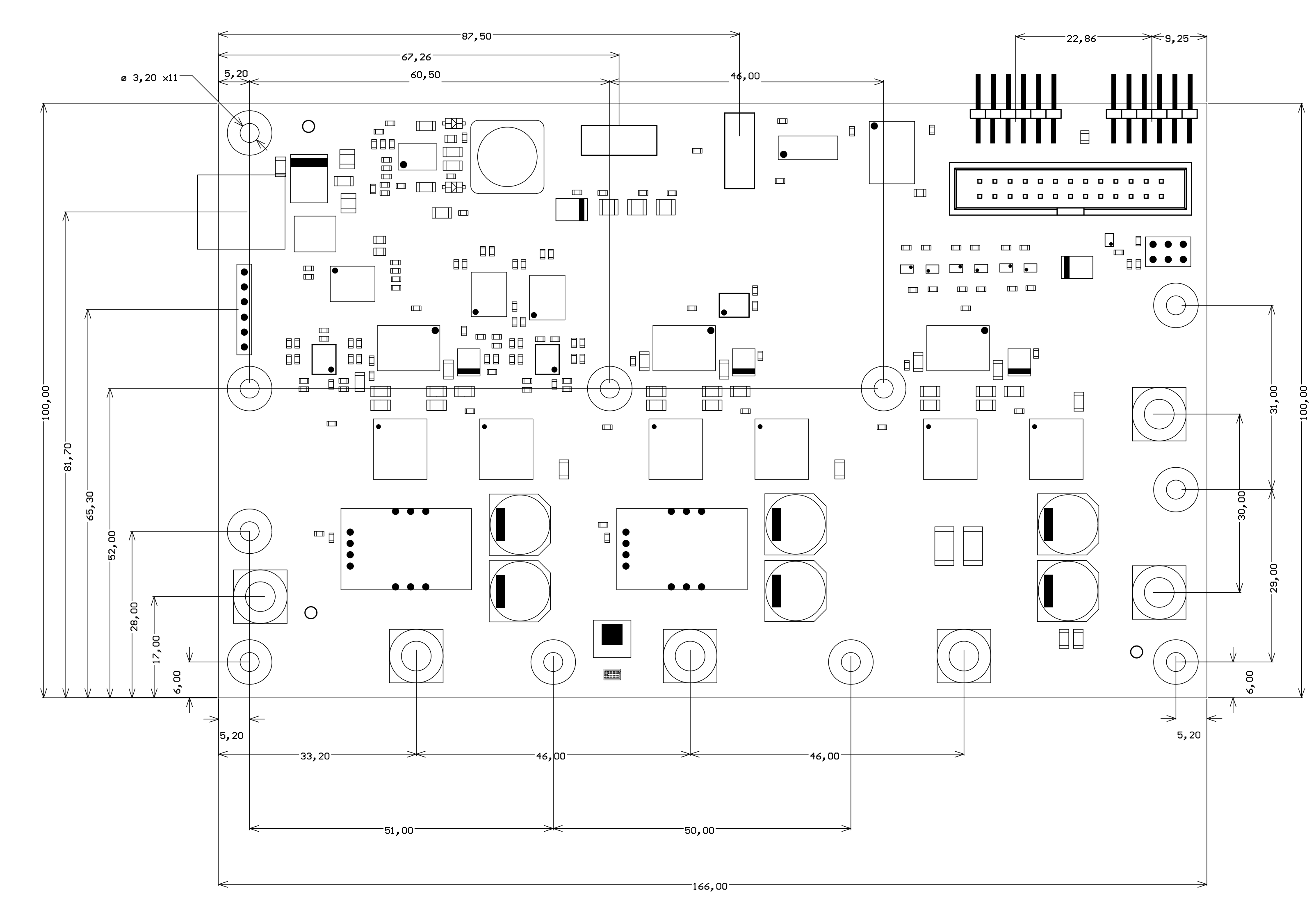
...
All dimensions are shown in mm. Additional sketches, drawings and schematics can be found TODO: here.
Operating Temperature Ranges - TODO
Weight - TODO
| Variant | Weight in g | Note |
|---|---|---|
| - | TODO |
|
Revision History
Hardware Revision History - TODO
| Date | Revision | Notes | PCN Link | Documentation Link |
|---|---|---|---|---|
| 2016-03-27 | 02 | TEC0053-02 | ||
| 2017-08-14 | 04 |
Hardware revision number is printed on the PCB board in the down right corner.
Document Change History - TODO
Date | Revision | Authors | Description |
|---|---|---|---|
| 2017-03-30 |
| Andreas Heidemann | Initial Version |
...
Overview
Content Tools