Page History
...
PMoD Cable installation, Pin 1 Markings highlighted, on Drive Board a white dot marks 6 Pin header Pin 1, also marked with "G" (ground). This pin should be aligned to Encoder Pin marked "G" and "1" visible when looking from the bottom up. Please note that Encoder header has 5 terminals while the driver board and PMoD cable have 6 terminals.
| Page break |
|---|
EDDP System Components
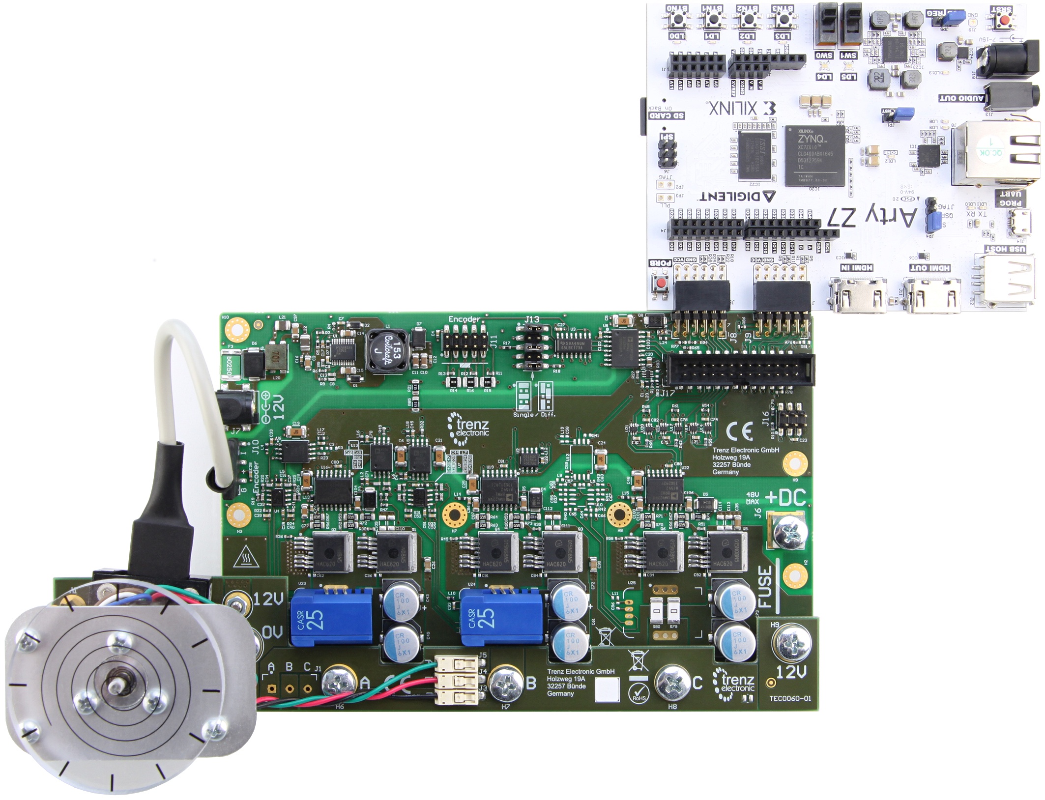
EDDP Kit Content
...
| Note |
|---|
The Motor is pre-mounted to the Driver board using the Adapter Board and accessories. |
Control Board
The default Control Board is the Digilent ARTY-Z 7010, which is delivered as part of the EDDP Kit. This manual contains information relevent to the actual use of the ARTY-Z as a Control Board within the EDDP only; all technical data and user guides and manuals for the Controller Board are provided by the controller board manufacturer (Digilent Inc.). Use of the other Control boards with the EDPS Driver board is also outside the scope of this manual. Primary support for other control boards is currently provided by QDESYS.
...
Overview
Content Tools