Page History
...
When delivered as full EDDP Kit several components are pre-assembled.
Motor connectionAdapter Board
The default (Refence) Motor with Encoder is connected to the Driver Board using special "Adapter Board" (TEC0060). In the EDDP Kit the Motor is pre-assembled:
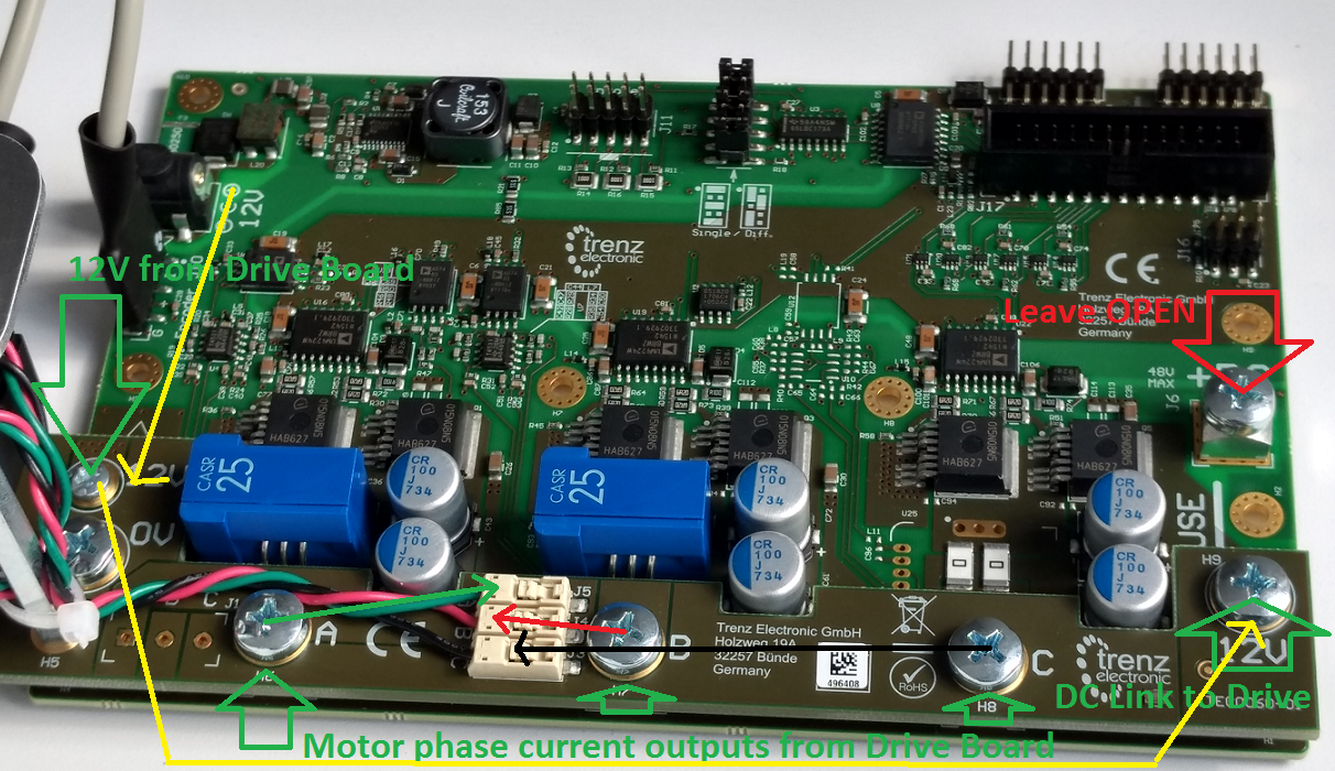
The Adapter board is mounted to Driver Board using 5 x M6 screws (Labels 0V, A, B, C, 12V on Adapter Board) and with M3 screws and spacer - marked 12V at the left. This Adapter board "forwards" the Drive board pre-driver supply (12V) to the DC Link main terminal on the Drive board, so that separate DC Link powersupply is not needed allowing easy evaluation of the complete system.
Motor Connection
When delivered as full EDDP Kit the reference Motor wires are already connected to Adapter board. Instructions for manual assembly below:
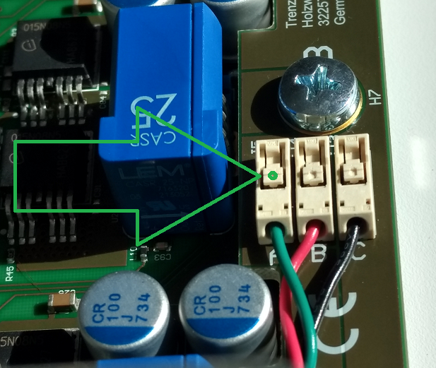
Green dot and Arrow mark the place where wire terminal can be released for insertion or removal. Use a ball-point pen or similar tool to apply gentle force at the dot. Please do not try to remove the wires by pulling them out! And do not apply force in other regions of the white plastic than the
Encoder Connection
One 6 Pin PMoD cable is included with the EDDP Kit, it is already assembled between encoder and Drive Board. Instructions for manual assembly below:
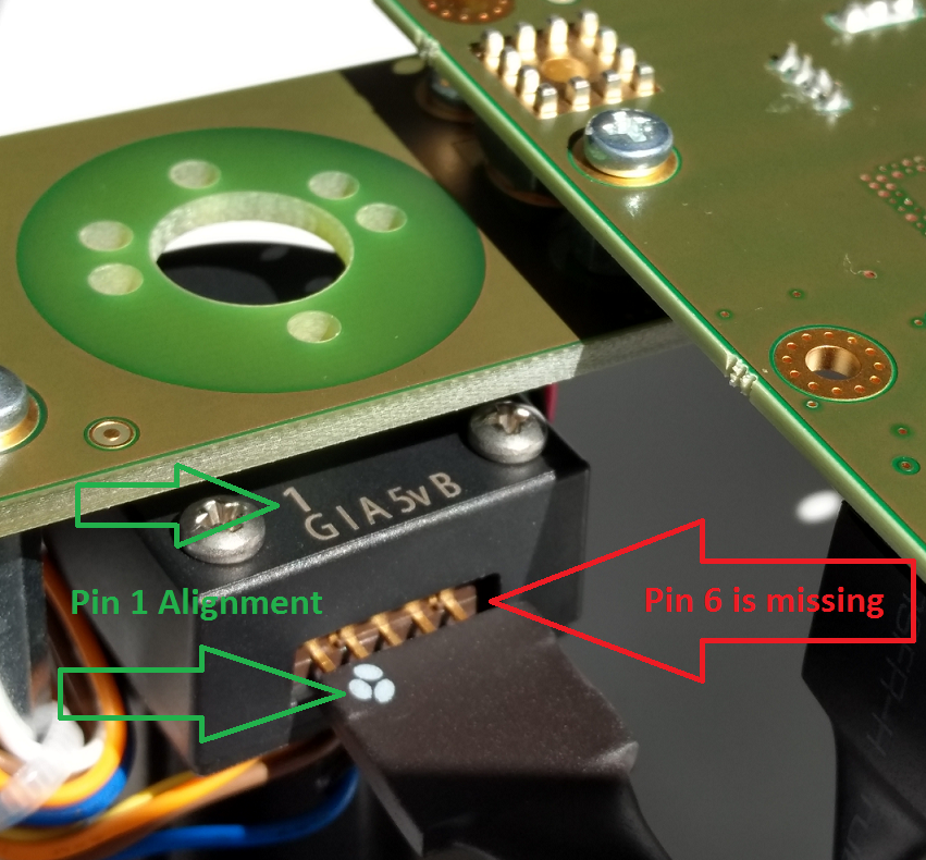
PMoD cable alignment to Encoder connector, notice that there are 5 pins in Encoder header while PMoD female connector has 6 terminals. Red Arrow marks the "empty" terminal at PMoD Cable.
...
Overview
Content Tools