Page History
...
The Adapter board is mounted to Driver Board using 5 x M6 screws (Labels 0V, A, B, C, 12V on Adapter Board) and with M3 screws and spacer - marked 12V at the left. This Adapter board "forwards" the Drive board pre-driver supply (12V) to the DC Link main terminal on the Drive board, so that separate DC Link powersupply is not needed allowing easy evaluation of the complete system.
Note terminal marked+DC must be left open when using the Adapter board!
M3 Spacer and screws connect 12V from from Drive board to Adapter Board.
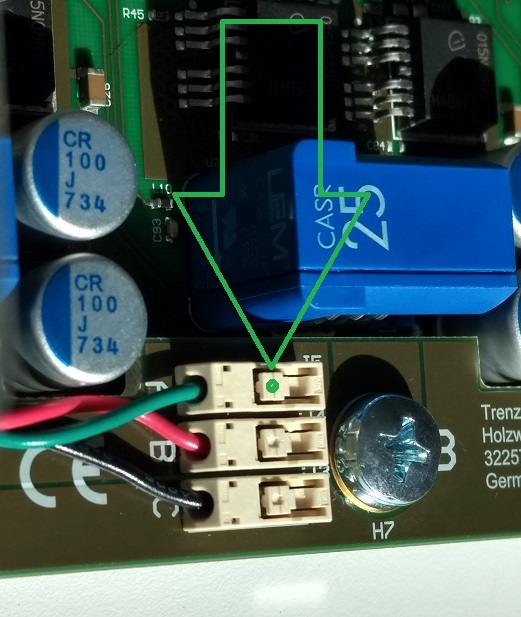
Motor Connection
When delivered as full EDDP Kit the reference Motor wires are already connected to Adapter board. Instructions for manual assembly below:
...
Overview
Content Tools