Page History
...
| Note |
|---|
Micro-SD is delivered without Linux images to avoid any issues related to US export control regulations. |
Hardware Assembly
When delivered as full EDDP Kit several components are pre-assembled.
...
The default (Reference) Motor with Encoder is connected to the Driver Board using special "Adapter Board" (TEC0060). In the EDDP Kit the Motor is pre-assembled:
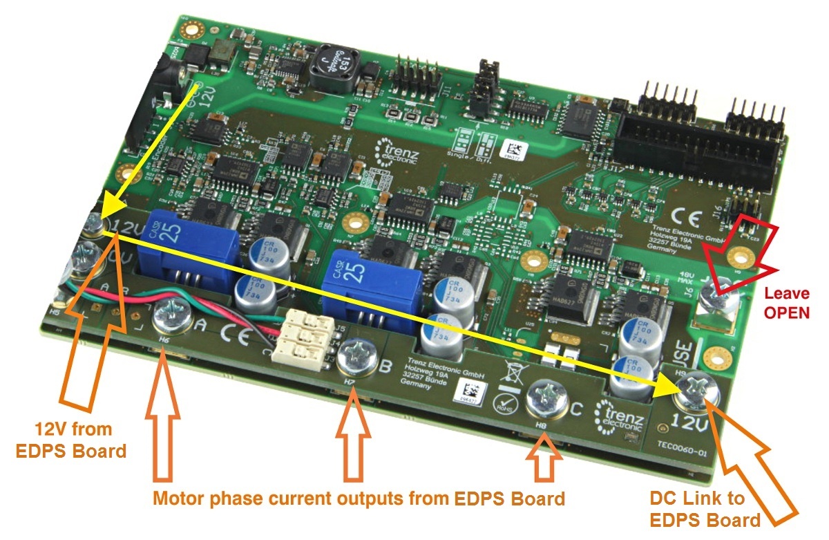
Figure 1: Top view of the TEC0060 PCB.
The Adapter board is mounted to Driver Board using 5 x M6 screws (Labels 0V, A, B, C, 12V on Adapter Board) and with M3 screws and spacer - marked 12V at the left. This Adapter board "forwards" (the yellow arrow) the Drive board pre-driver supply (12V) to the DC Link main terminal on the Drive board, so that separate DC Link powersupply is not needed allowing easy evaluation of the complete system.
Note terminal marked+DC must be left open when using the Adapter board!
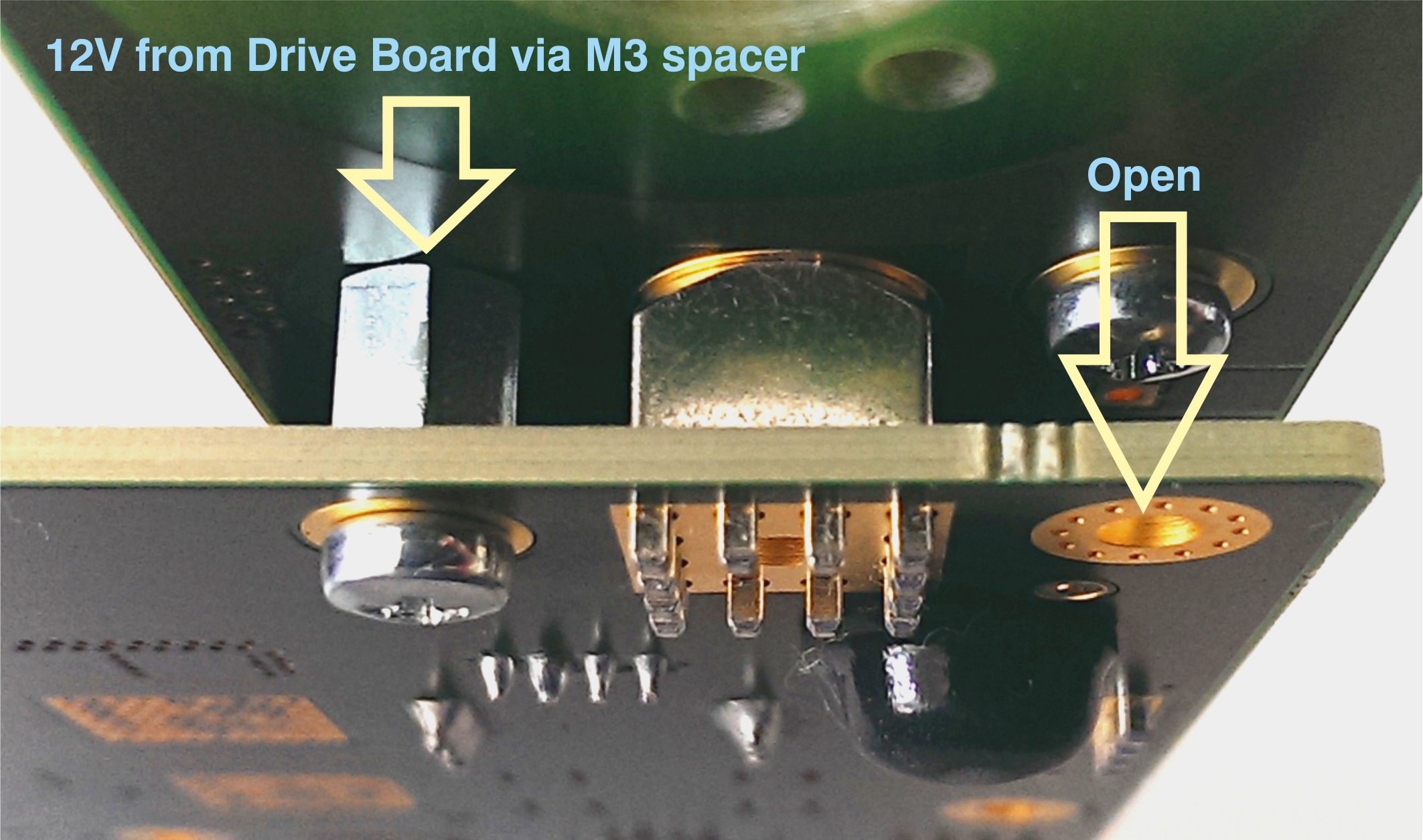
Figure 2: M3 spacer and two M3 screws connect 12V from Drive board to Adapter board.
...
Motor Connection
When delivered as full EDDP Kit the reference Motor wires are already connected to Adapter board. Instructions for manual assembly below:
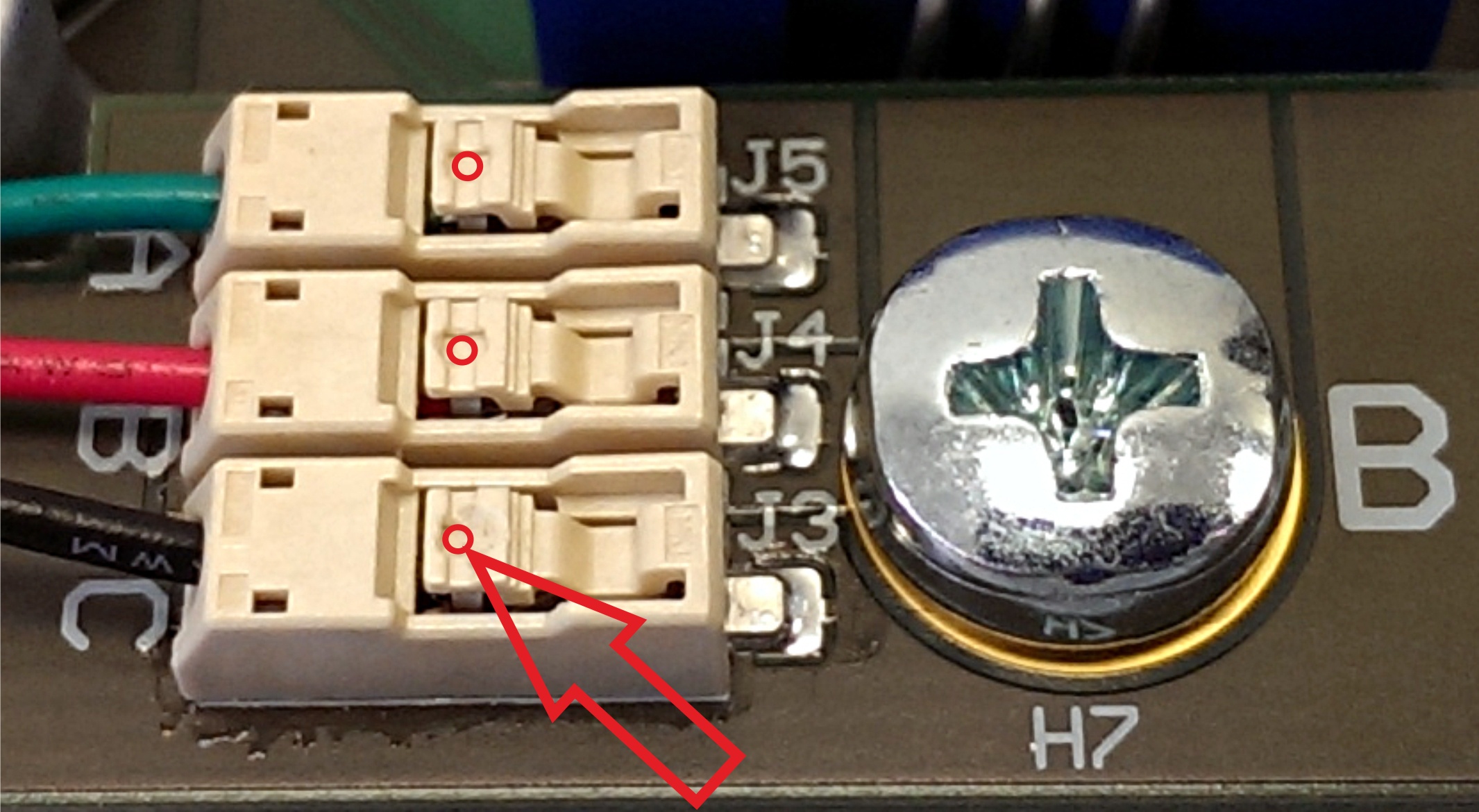
Figure 3: .
Red dots and arrow mark the place where wire terminal can be released for insertion or removal. Use a ball-point pen or similar tool to apply gentle force at the dot. Please do not try to remove the wires by pulling them out! Do not apply force in other regions of the white plastic than the one marked it is easy to damage the plastic.
...
One 6 Pin Pmod cable is included with the EDDP Kit, it is already assembled between encoder and Drive Board. Instructions for manual assembly below:
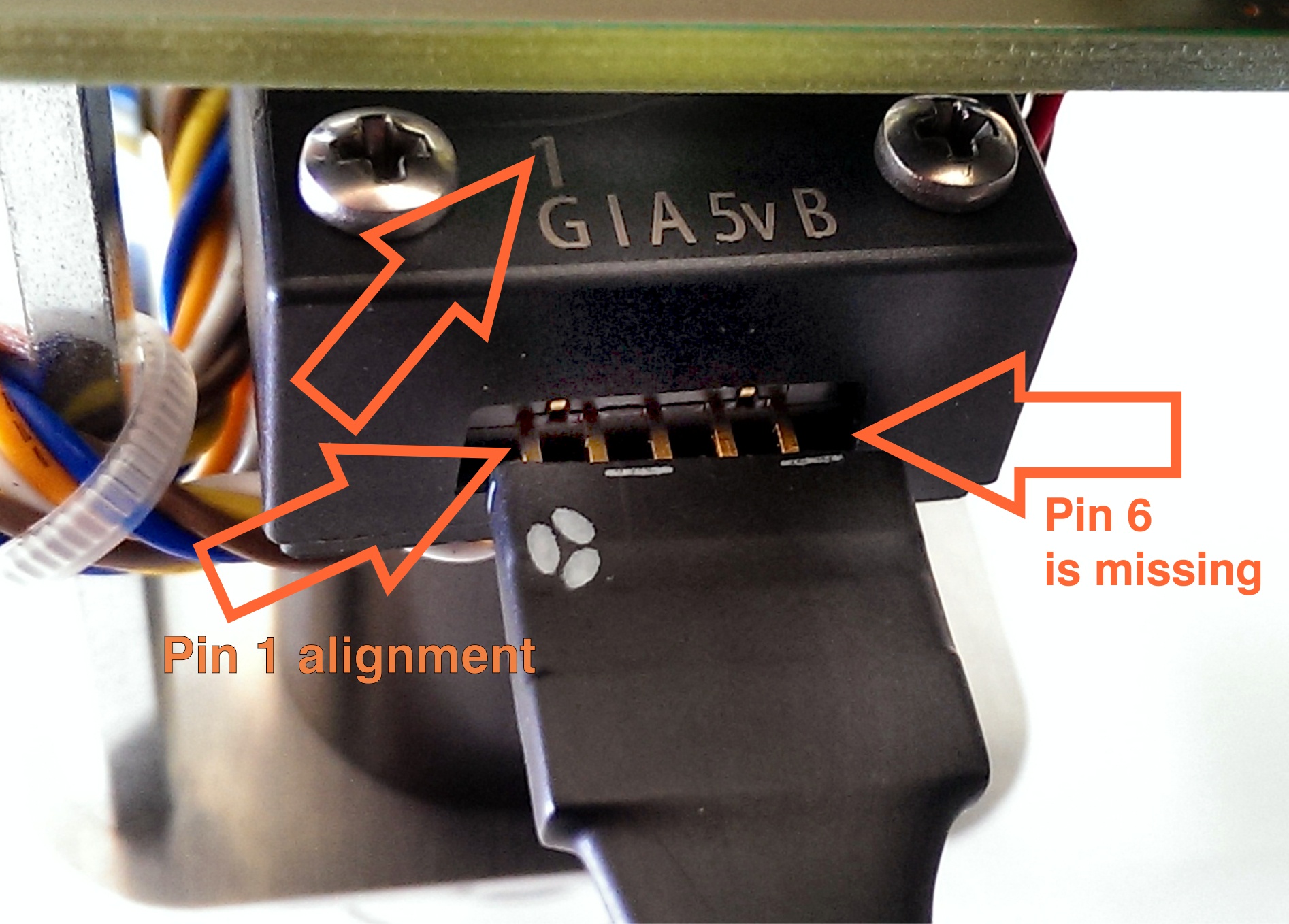
Figure 4: .
PMoD cable alignment to Encoder connector, notice that there are 5 pins in Encoder header while PMoD female connector has 6 terminals. Red Arrow marks the "empty" terminal at PMoD Cable.
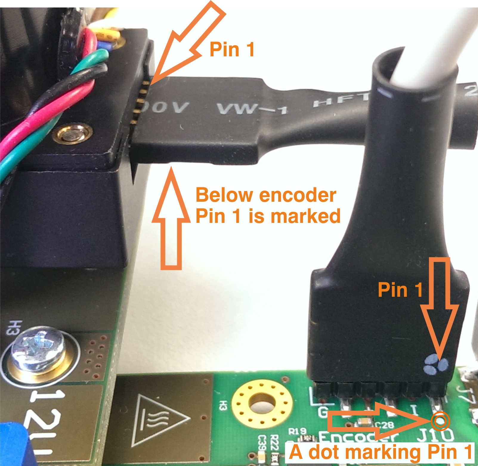
Figure 5: .
Pmod cable PMoD Cable installation, Pin pin 1 Markings markings highlighted, on Drive Board a white dot marks 6 Pin header Pin 1, also marked with "G" (ground). This pin should be aligned to Encoder Pin marked "G" and "1" visible when looking from the bottom up. Please note that Encoder header has 5 terminals while the driver board and PMoD cable have 6 terminals.
| Page break |
|---|
EDDP System Components
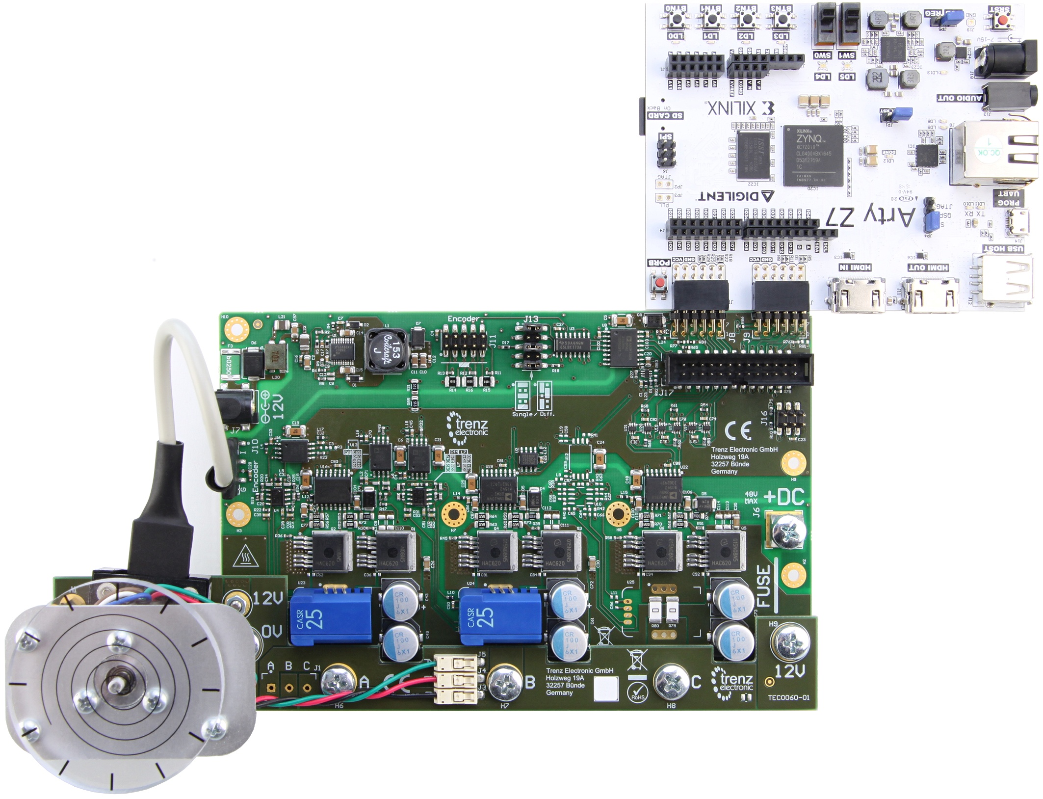
Figure 6: .
EDDP Kit Content
- Control Board: ARTY-Z-7010
- EDPS Driver Board: TEC0053
- EDPS Motor Adapter Board: TEC0060
- EDPS Reference Motor with Encoder: BLRW-111D-24V-10000-1000-SI
- Plastic DEMO load for Motor
- One 6 Pin PMoD cable
- Two 12V Power Supplies
- Screws and other accessories used to mount the motor
- One spare M6 Screw
- Plastic cover for Driver Board use without TEC0060
- 30A Fuse for Driver Board use without TEC0060
- Micro SD Card
- Quickstart Guide
...
To access the Web UI, point a web browser to the IP of the Controller Board. The following page appears:
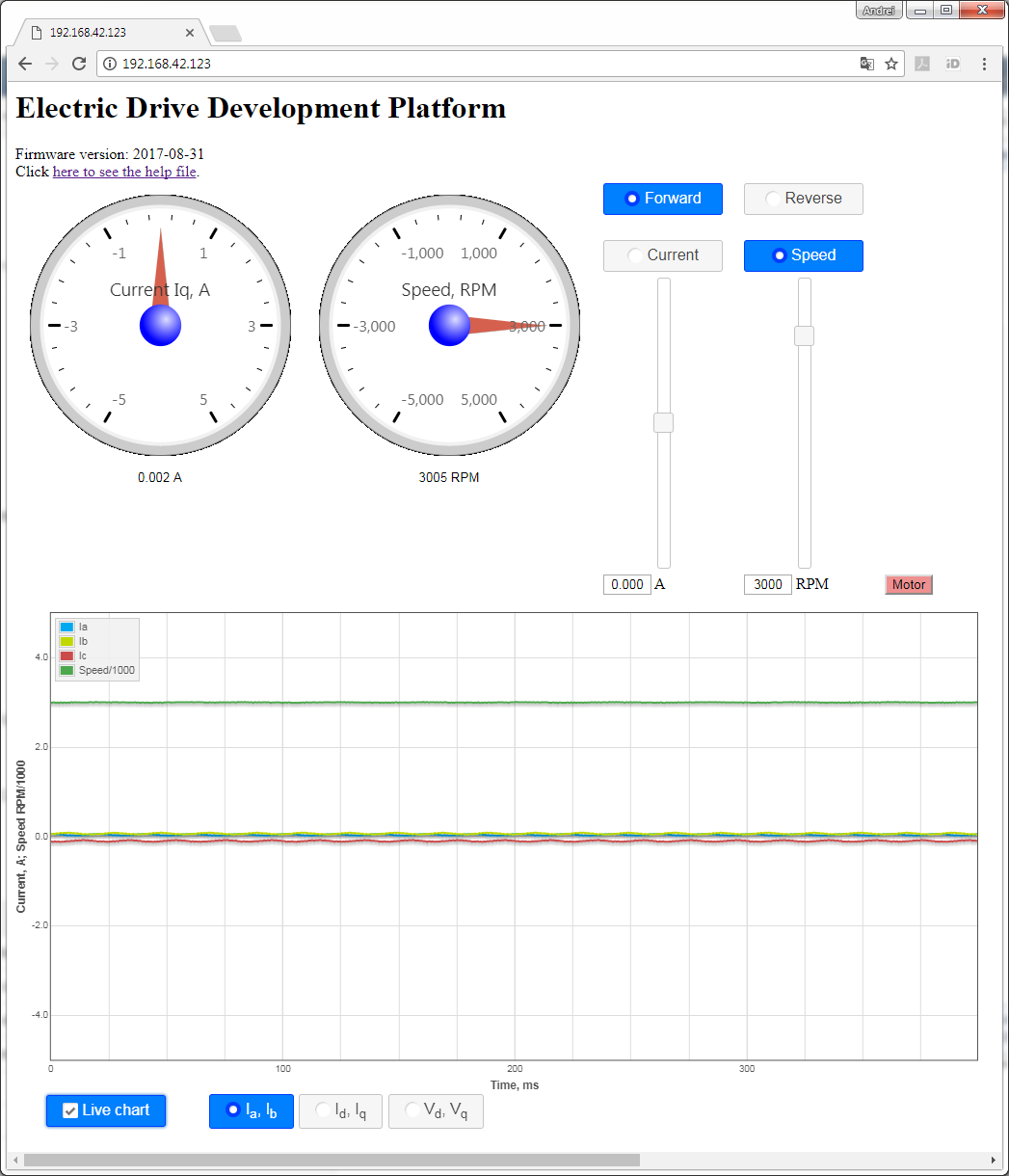
Figure 7: .
To start the motor, click the button "Motor". The motor will make 3 rotations in order to make sure that encoder finds the initial position before starting in correct mode and the button will turn red. To stop the motor, click the button "Motor" again; the button will turn green.
...
The default motor is supplied in the EDDP Kit; see the chapter Reference Motor for details. Use of custom motors is outside the scope of this manual.
Block Diagram
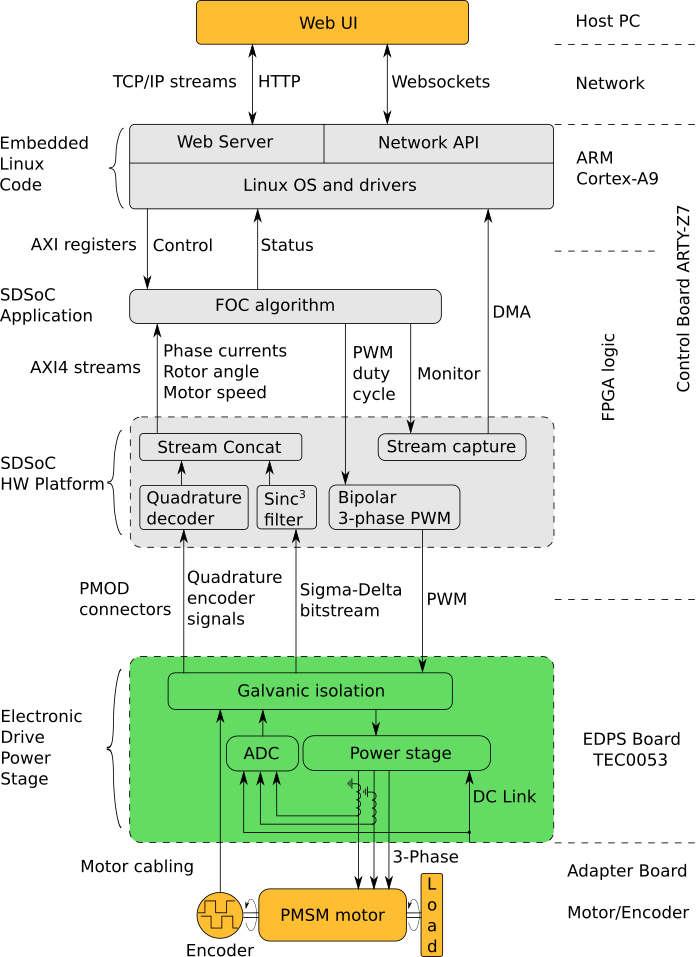
Figure 8: Block diagram of the TEC0060.
Functional description
A 3-phase permanent-magnet synchronous motor with attached encoder and mechanical load is mounted to a EDPS Driver Board TEC0053 by using an Adapter Board TEC0060. The Driver Board is connected to a Control Board ARTY-Z7 through PMOD connectors. A Host PC running a Web Browser connects to the Control Board through a Network.
...
- The Linux OS manages the hardware and provides execution environment for the programs to run in, which includes a TCP/IP network stack. The drivers included provide access to the control and status registers of the FOC algorithm and to the DMA buffer of the monitor data stream.
- The Network API is a server program, which provides an API built on top of Websockets protocol to control and monitor the FOC algorithm and to capture the monitor data stream.
- The Web Server, which is used to host the Web UI.
The Web UI running in a web browser on the Host PC enables one to operate use of the EDDP Kit from anywhere in a the network.
List of the additional documents for further information:
| Title | Description |
|---|---|
| FOC SDSoC | Implementation of a Field-Oriented Control algorithm in C++ with Vivado SDSoC |
| SDSoC Hardware Platform ARTY-Z7 | A basis for building Vivado SDSoC applications running on an Arty-Z7 board connected to a TEC0053 board |
| AXI4-Stream AD7403 | An IP core for filtering the delta-sigma bitstream read from one or more ADC-s of type of AD7403 to an AXI4-Stream of samples |
| AXI4-Stream Encoder | An IP core for converting impulses from a relative index encoder with an index signal to an AXI4-Stream of position and speed data |
| AXI4-Stream PWM | An IP core for generating PWM signals according to the input AXI4-Stream |
| AXI4-Stream Concat | An IP core for concatenating AXI4-Streams |
| Web GUI | A Web UI to control and monitor an EDPS board over the Network API |
| Network API | A communication protocol, based on Websockets, to control an EDPS board |
| Embedded Linux Code | A server program interfacing to an EDPS board and implementing the Network API and the functions of a Web Server |
Table 1: List of the additional documents.
References
All resource links for other relevant documents and websites are available from Trenz EDDP Web Hub:
...
Date | Revision | Contributors | Description | ||||||||
|---|---|---|---|---|---|---|---|---|---|---|---|
| Jan Kumann | General formatting changes and small corrections. | |||||||||
2017-08-14 | v.10 | Antti Lukats, Andrei Errapart | Initial document. |
Table 2: Document change history.
| Include Page | ||||
|---|---|---|---|---|
|
Overview
Content Tools