Page History
...
Motor Connection
When delivered as full EDDP Kit the reference Motor wires are already connected to Adapter board. Instructions for manual assembly below:
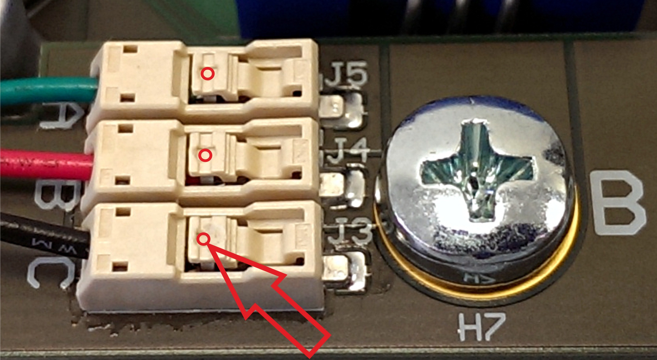
Figure 3: .
Red dots and arrow mark the place where wire terminal can be released for insertion or removal.
Use Use a ball-point pen or similar tool to apply gentle force at the dot. Please do not try to remove the wires by pulling them out! Do not apply force in any other regions region of the white plastic than the one except as marked, it is easy to damage the plastic.
Encoder Connection
One 6 Pin -pin Pmod cable is included with the EDDP Kit, it . It is already assembled between encoder and Drive Board. Instructions for manual assembly are below:
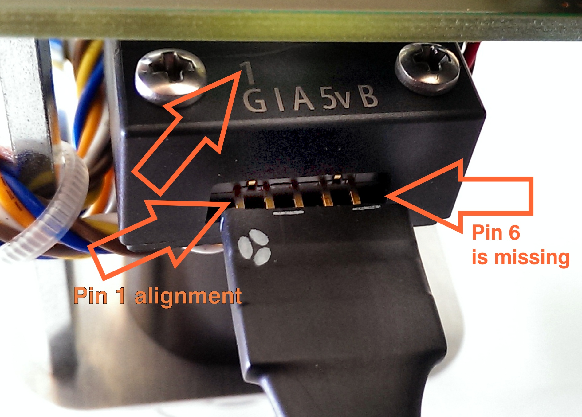
Figure 4: .PMoD Pmod cable alignment to Encoder connector.
Notice , notice that there are 5 pins in Encoder header while PMoD female connector has 6 terminals. Red Arrow marks the "empty" terminal at PMoD Cable.
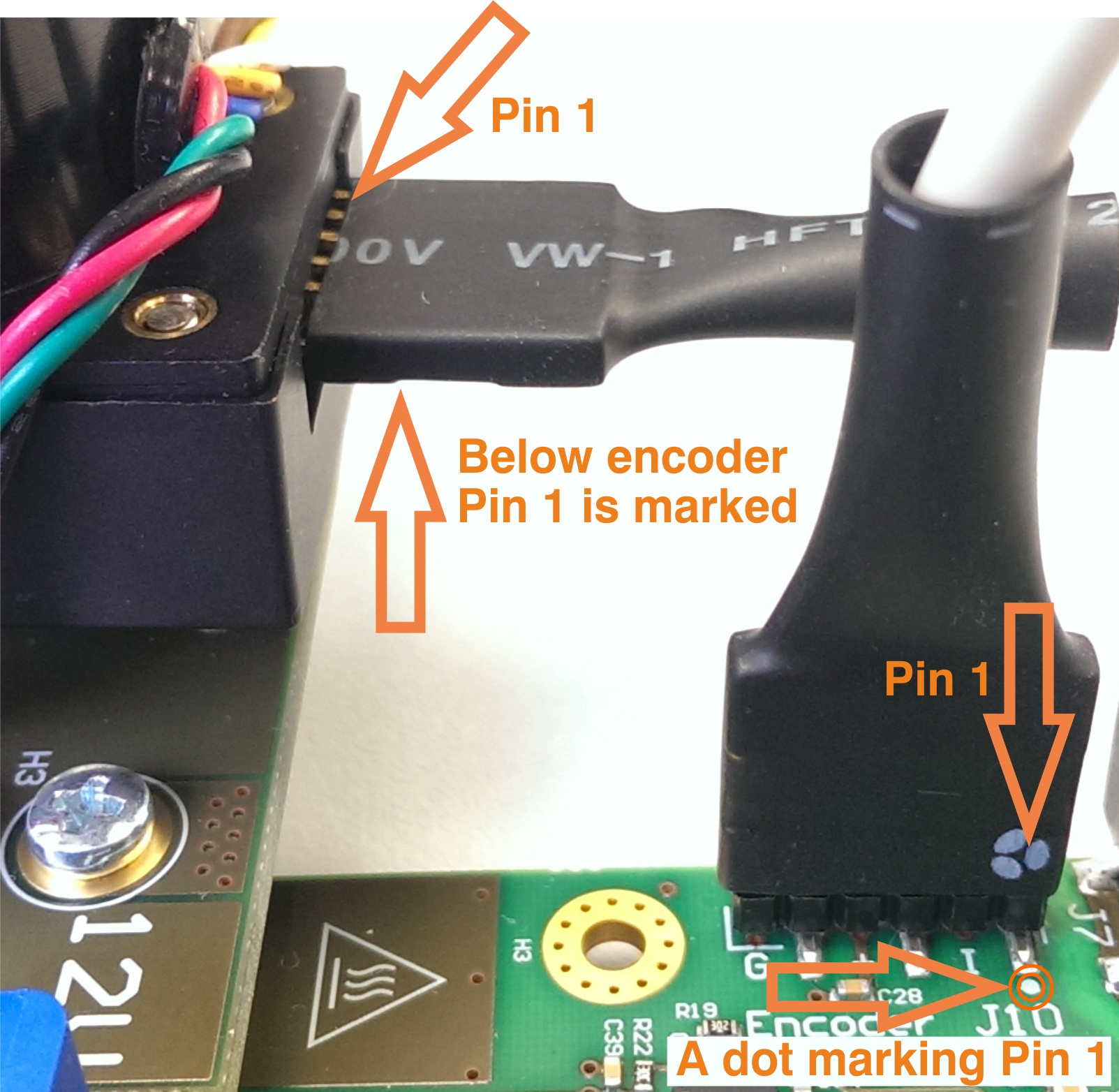
Figure 5: . Pmod cable installation.
Pin , pin 1 markings highlightedare indicated with the arrows, on the Drive Board a white dot marks 6 Pin -pin Pmod header Pin 1, also marked with "G" (ground)pin 1. This pin should be aligned to Encoder Pin marked "G" and "1" visible when looking from the bottom up. Please note that Encoder header has 5 terminals while the driver board and PMoD Pmod cable have 6 terminals.
| Page break |
|---|
EDDP System Components
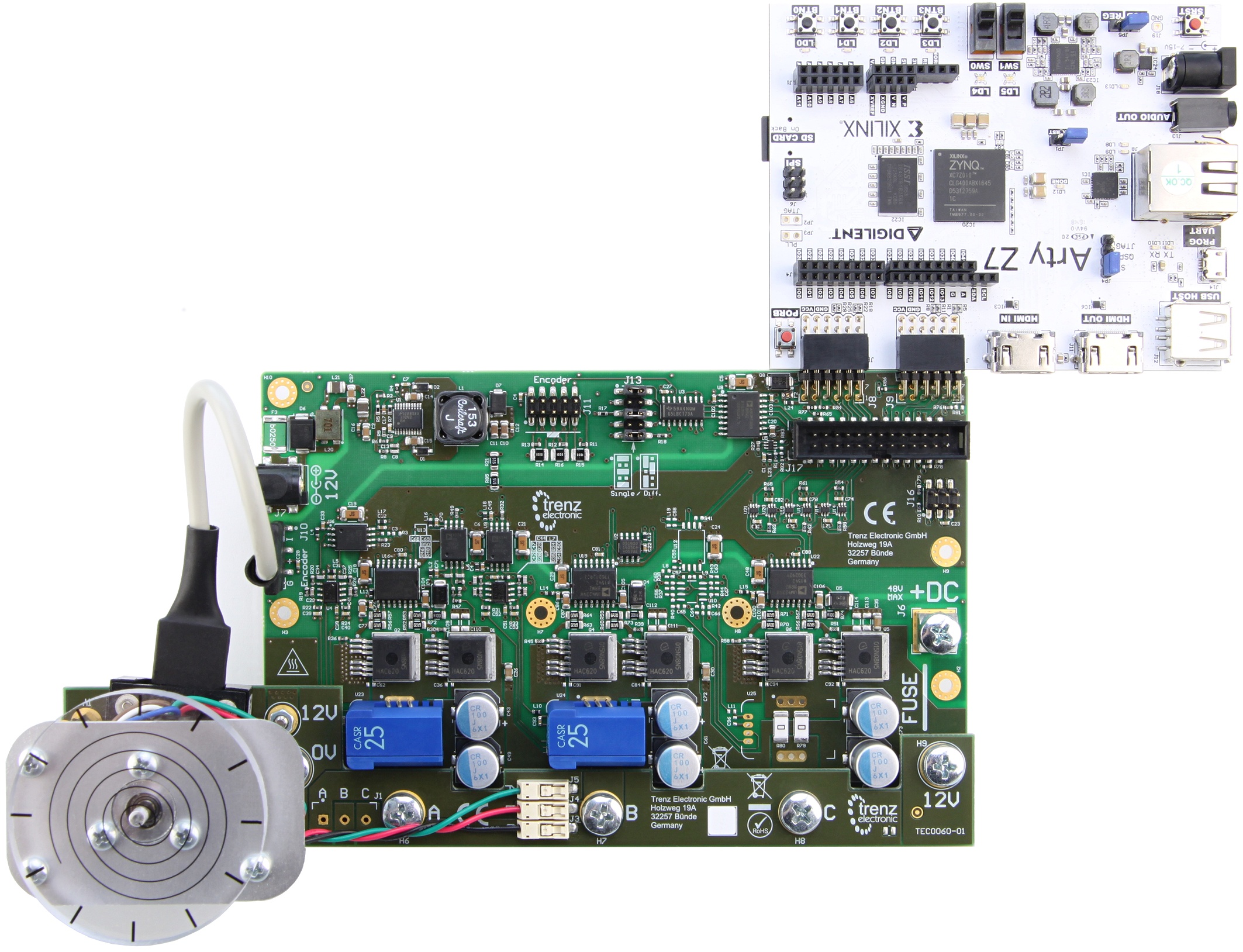
Figure 6: EDDP Kit assembly.
EDDP Kit Content
- Control Board: ARTY-Z-7010
- EDPS Driver Board: TEC0053
- EDPS Motor Adapter Board: TEC0060
- EDPS Reference Motor with Encoder: BLRW-111D-24V-10000-1000-SI
- Plastic DEMO load for Motor
- One 6 Pin PMoD cable
- Two 12V Power Supplies
- Screws and other accessories used to mount the motor
- One spare M6 Screw
- Plastic cover for Driver Board use without TEC0060
- 30A Fuse for Driver Board use without TEC0060
- Micro SD Card
- Quickstart Guide
...
The software delivered on the SD card configures the FPGA on the ARTY-Z board with the Field-Oriented Control algorithm and starts the web server to serve the Web User Interface (Web UI).
To access the EDDP Web UI, point a web browser to the IP enter IP address of the Controller Board to the web browser address field. The following page appears:
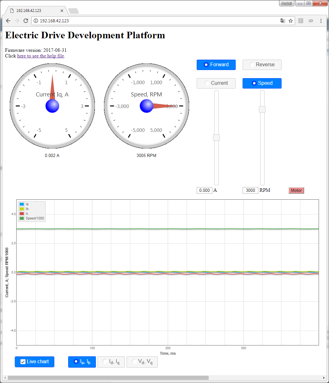
Figure 7: EDDP web UI.
To start the motor, click the button "Motor". The motor will make 3 rotations in order to make sure that encoder finds the initial position before starting in correct mode and the button will turn red. To stop the motor, click the button "Motor" again; the button will turn green.
...
Overview
Content Tools