Page History
...
The default (Reference) Motor with Encoder is connected to the Driver Board using special "Adapter Board" (TEC0060). In the EDDP Kit the Motor is pre-assembled:
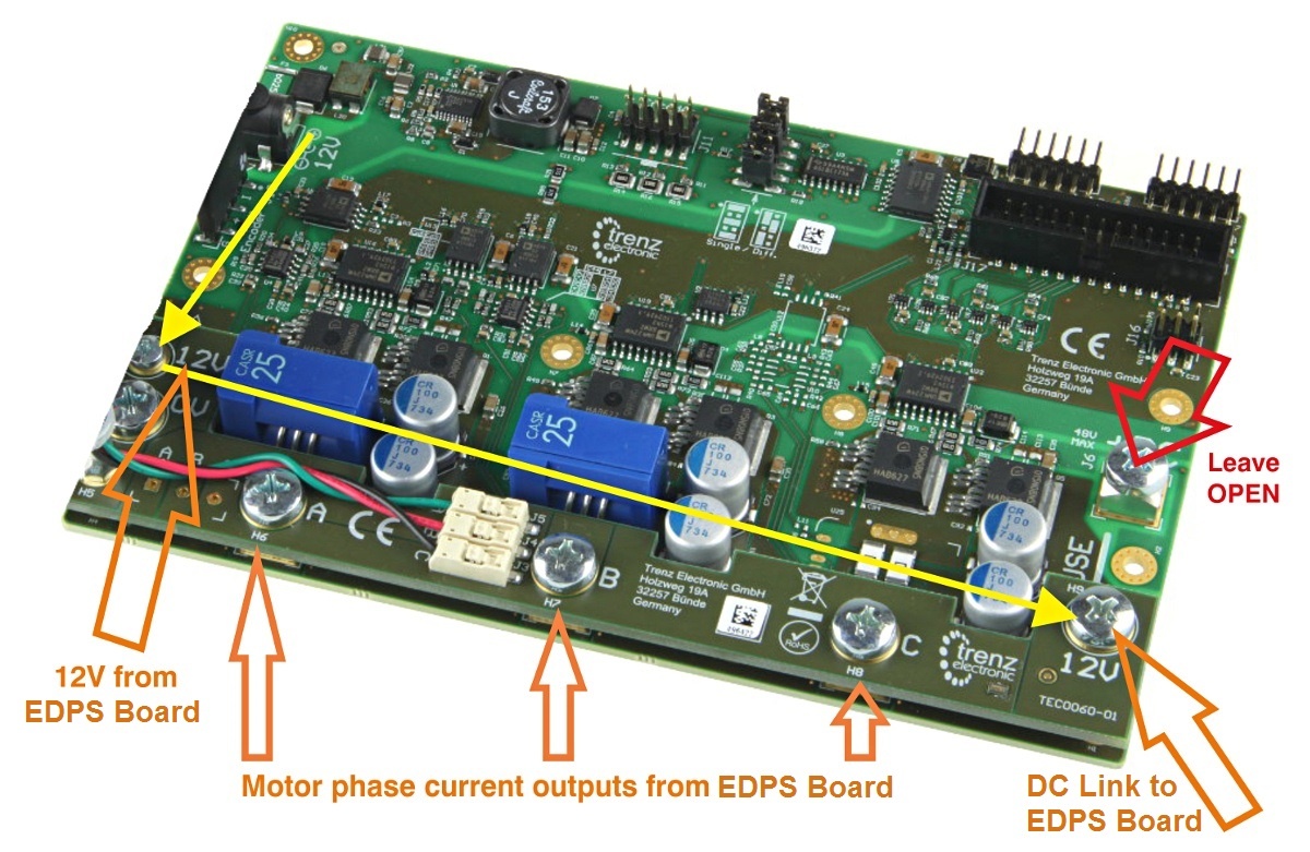
Figure 1: Top view of the TEC0060 PCB.
...
Note terminal marked+DC must be left open when using the Adapter board!
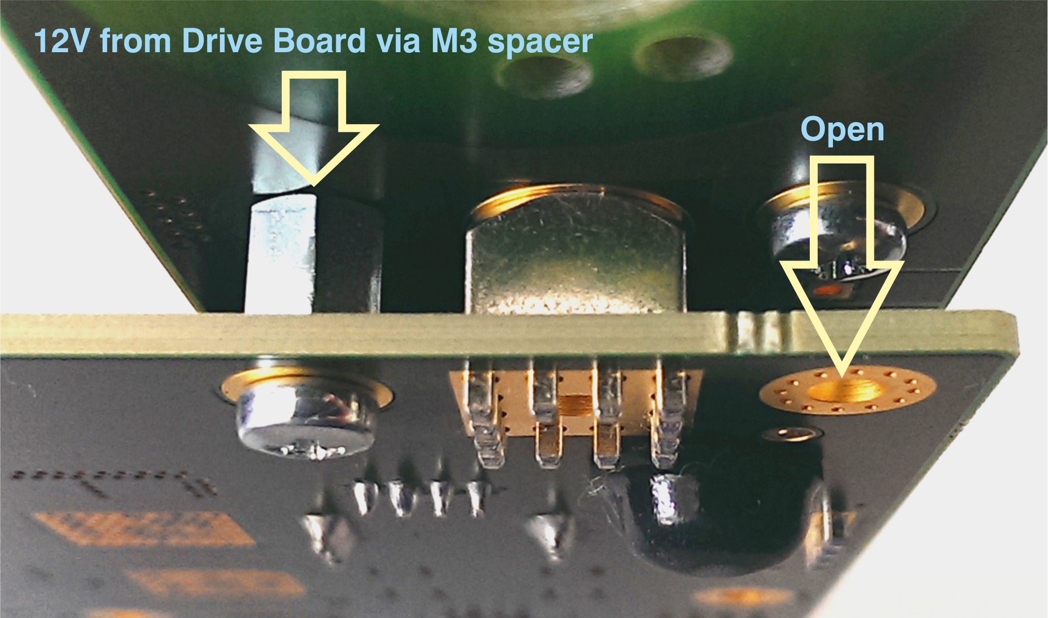
Figure 2: M3 spacer and two M3 screws connect 12V from Drive board to Adapter board.
...
Motor Connection
When delivered as full EDDP Kit the reference Motor wires are already connected to Adapter board. Instructions for manual assembly below:
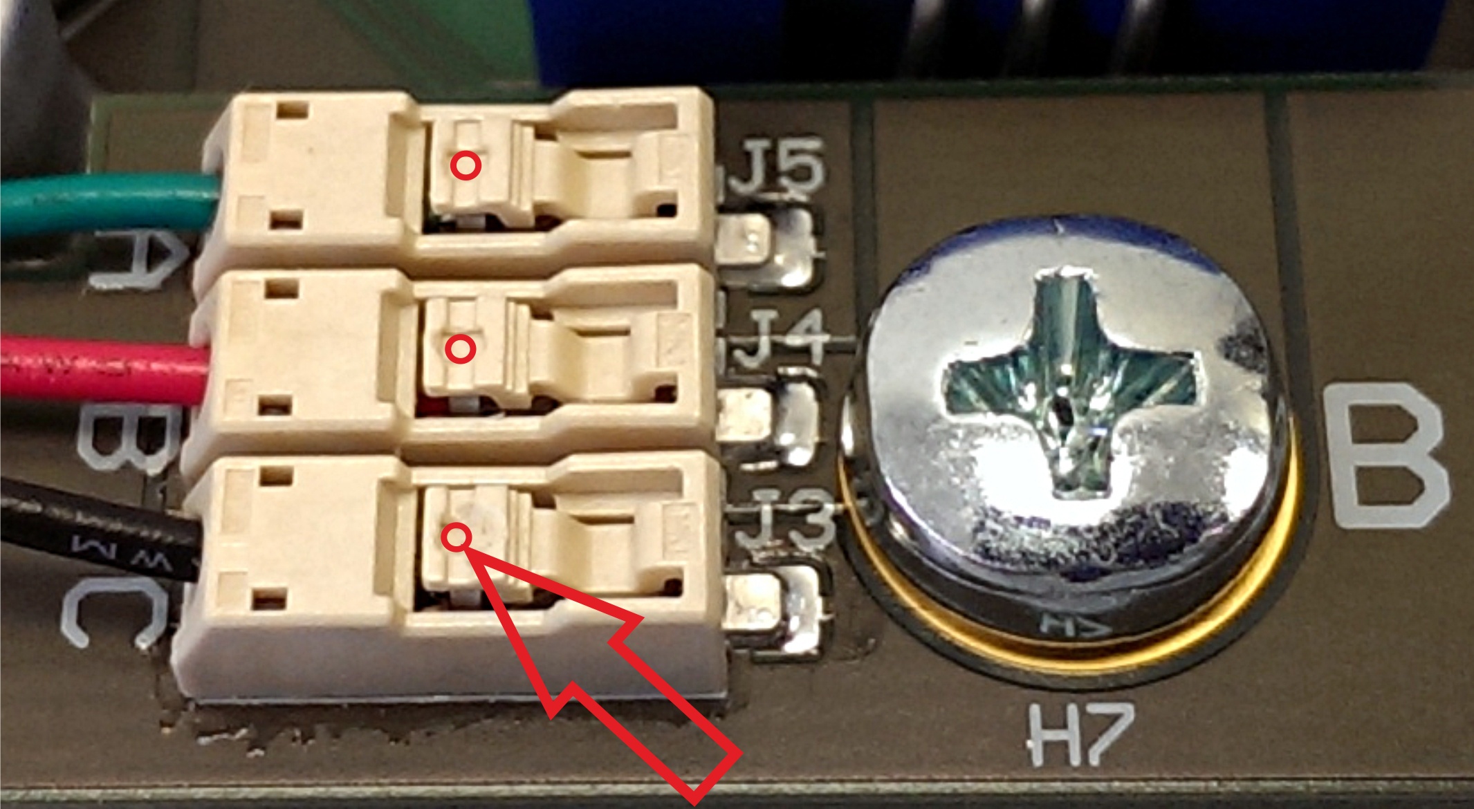
Figure 3: Red dots and arrow mark the place where wire terminal can be released for insertion or removal.
...
One 6-pin Pmod cable is included with the EDDP Kit. It is already assembled between encoder and Drive Board. Instructions for manual assembly are below:
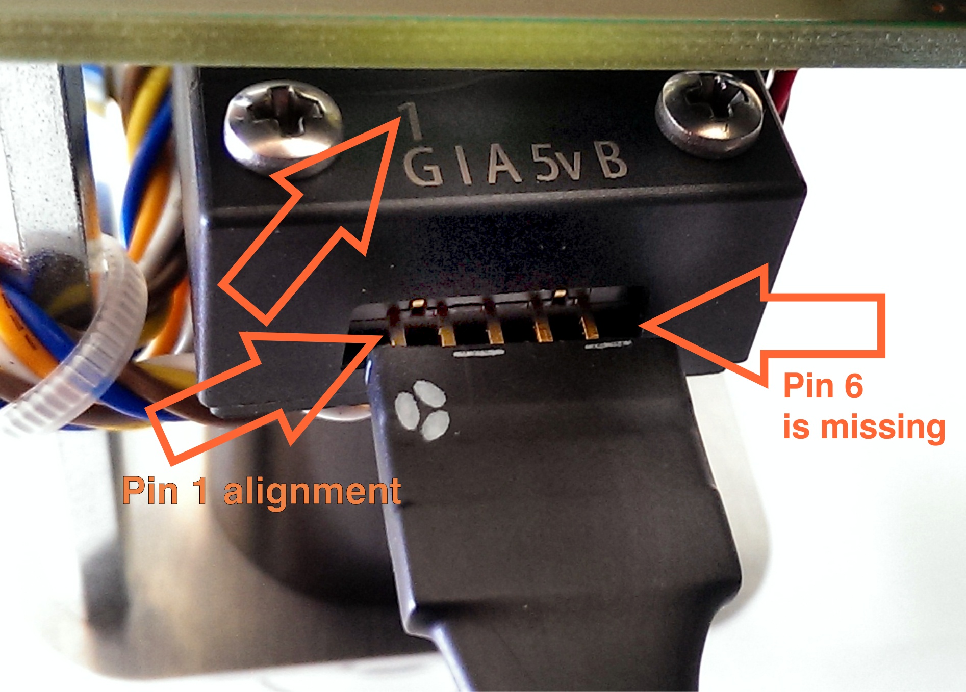
Figure 4: Pmod cable alignment to Encoder connector.
Notice that there are 5 pins in Encoder header while PMoD female connector has 6 terminals. Red Arrow marks the "empty" terminal at PMoD Cable.
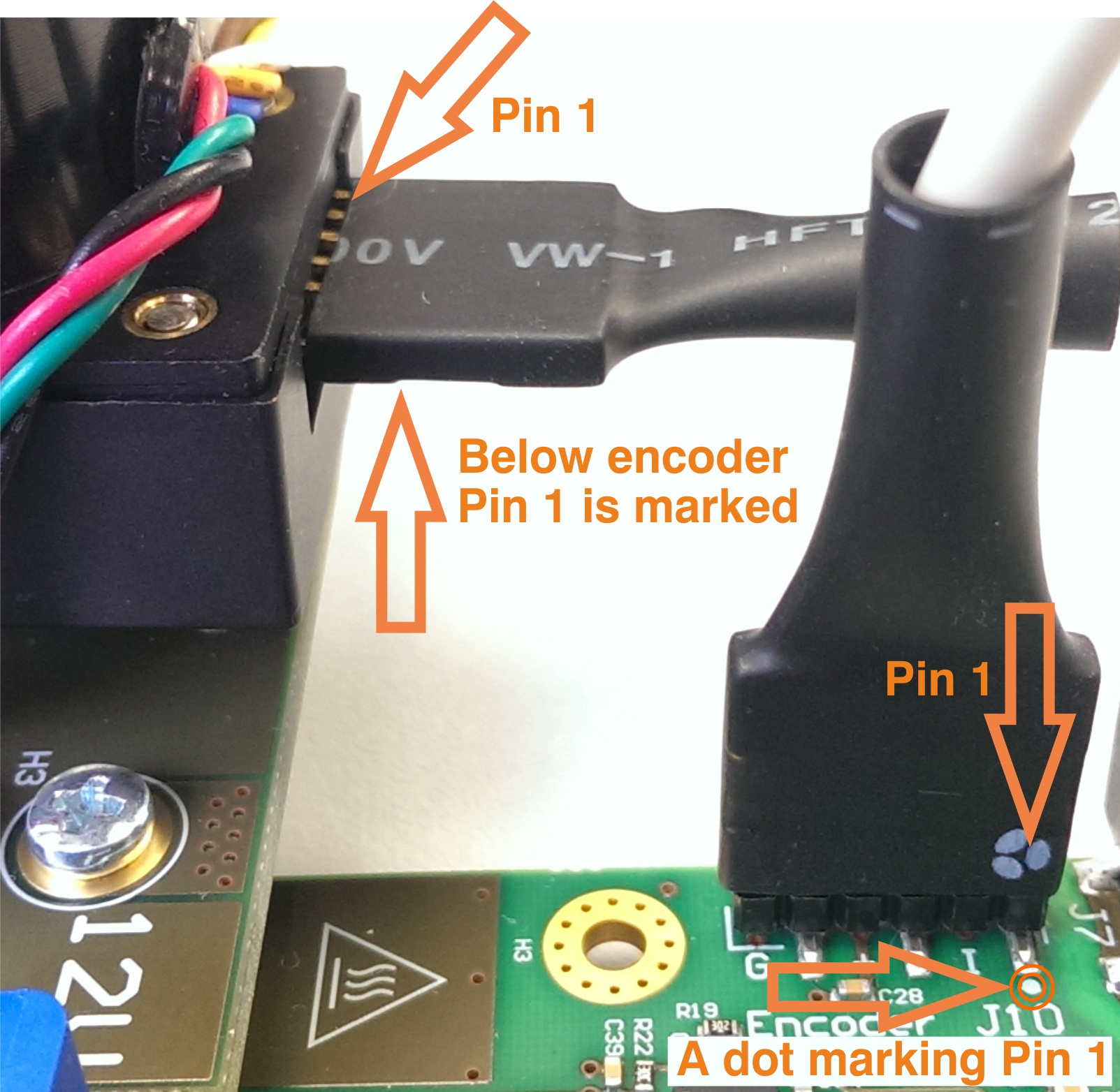
Figure 5: Pmod cable installation.
...
| Page break |
|---|
EDDP System Components
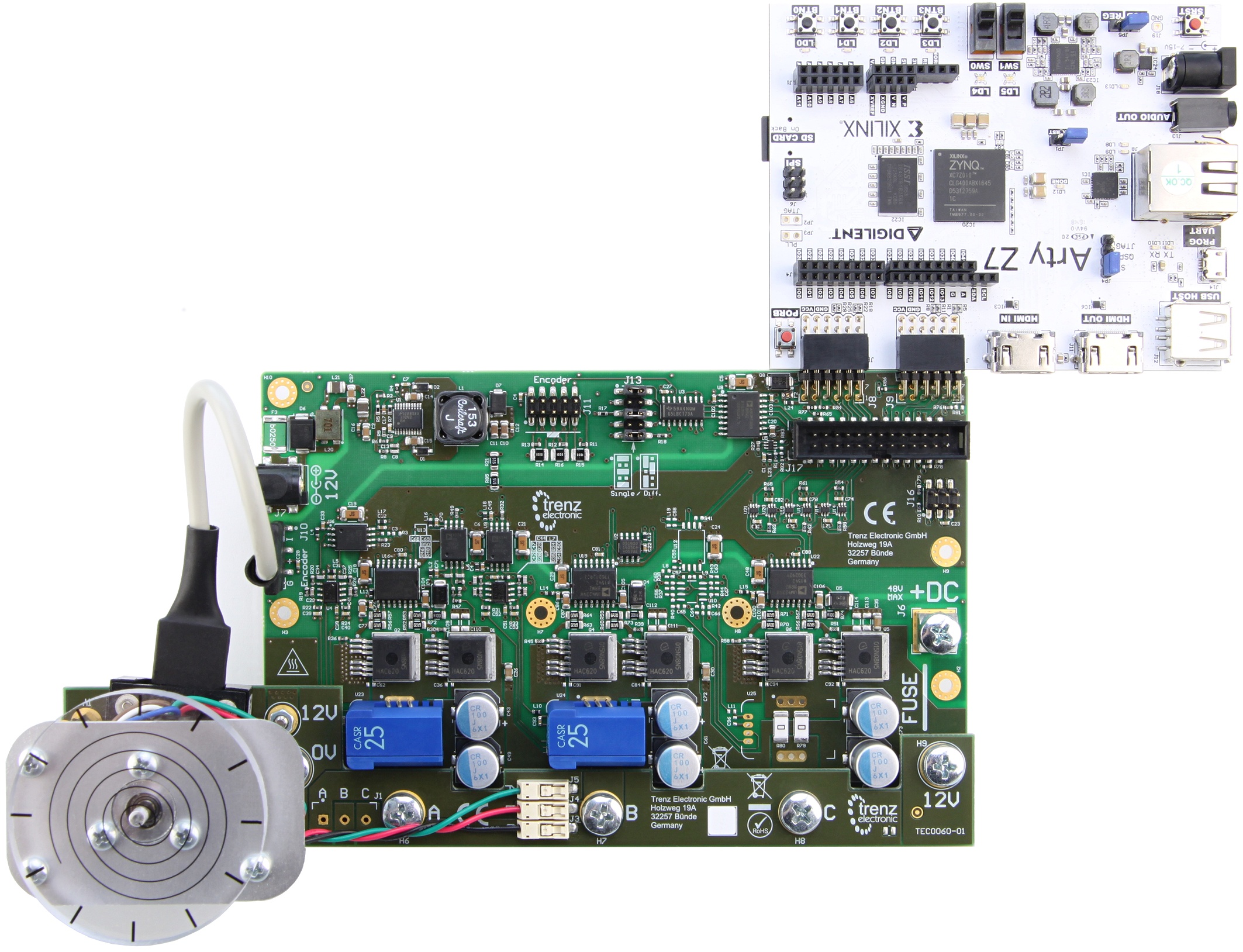
Figure 6: EDDP Kit assembly.
...
The default motor is supplied in the EDDP Kit; see the chapter Reference Motor for details. Use of custom motors is outside the scope of this manual.
Block Diagram
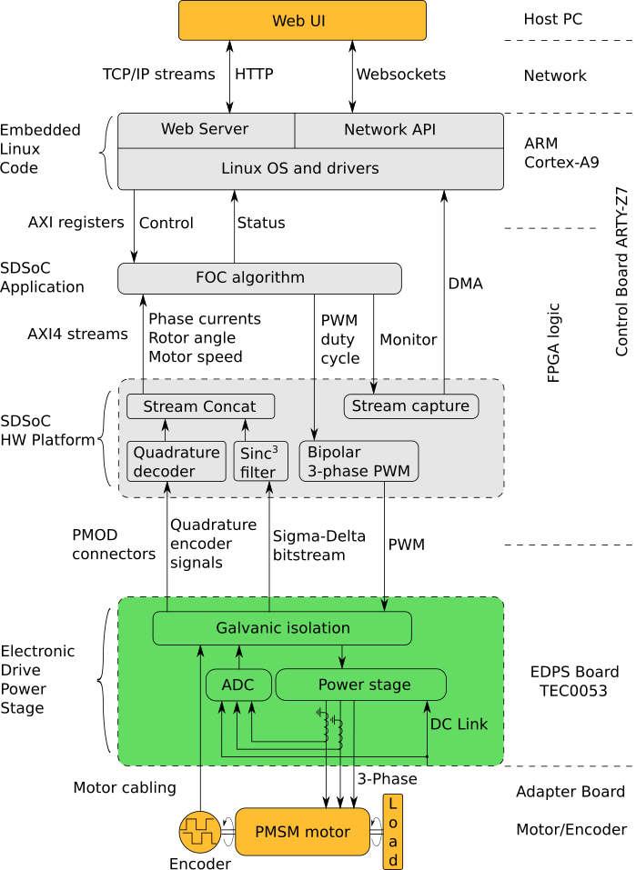
Figure 8: Block diagram of the TEC0060.
...
Overview
Content Tools