Page History
...
When delivered as full EDDP Kit several components are pre-assembled.
Motor Adapter Board
The default (Reference) Motor with Encoder is connected to the Driver Board using special "Adapter Board" (TEC0060). In the EDDP Kit the Motor is pre-assembled:
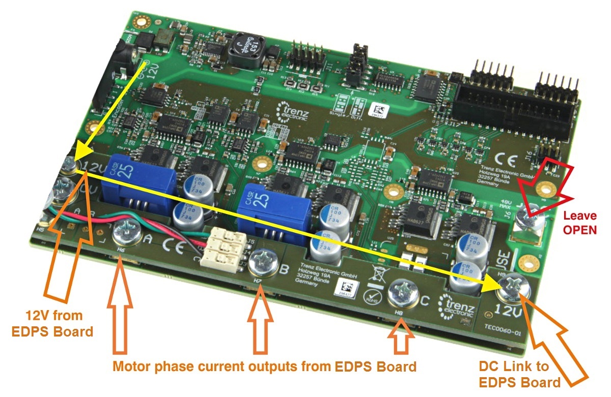
Figure 1: Top view of the TEC0060 PCBEDDP Board.
The Adapter board is mounted to Driver Board using 5 x M6 screws (Labels 0V, A, B, C, 12V on Adapter Board) and with M3 screws and spacer - marked 12V at the left. This Adapter board "forwards" (the yellow arrow) the Drive board pre-driver supply (12V) to the DC Link main terminal on the Drive board, so that separate DC Link powersupply power supply is not needed allowing easy evaluation of the complete system.
| Scroll Pagebreak |
|---|
Note terminal marked+DC must be left open when using the Adapter board!
...
Figure 2: M3 spacer and two M3 screws connect 12V from Drive board to Adapter board.
Motor Connection
When delivered as full EDDP Kit the reference Motor wires are already connected to Adapter board. Instructions for manual assembly below:
...
Use a ball-point pen or similar tool to apply gentle force at the dot. Please do not try to remove the wires by pulling them out! Do not apply force in any other region of the white plastic except as marked, it is easy to damage the plastic.
Encoder Connection
One 6-pin Pmod cable is included with the EDDP Kit. It is already assembled between encoder and Drive Board. Instructions for manual assembly are below:
...
Figure 4: Pmod cable alignment to Encoder connector.
Notice that there are 5 pins in Encoder header while PMoD female connector has 6 terminals. Red Arrow marks the "empty" terminal at PMoD Cable.
...
| Page break |
|---|
EDDP System Components
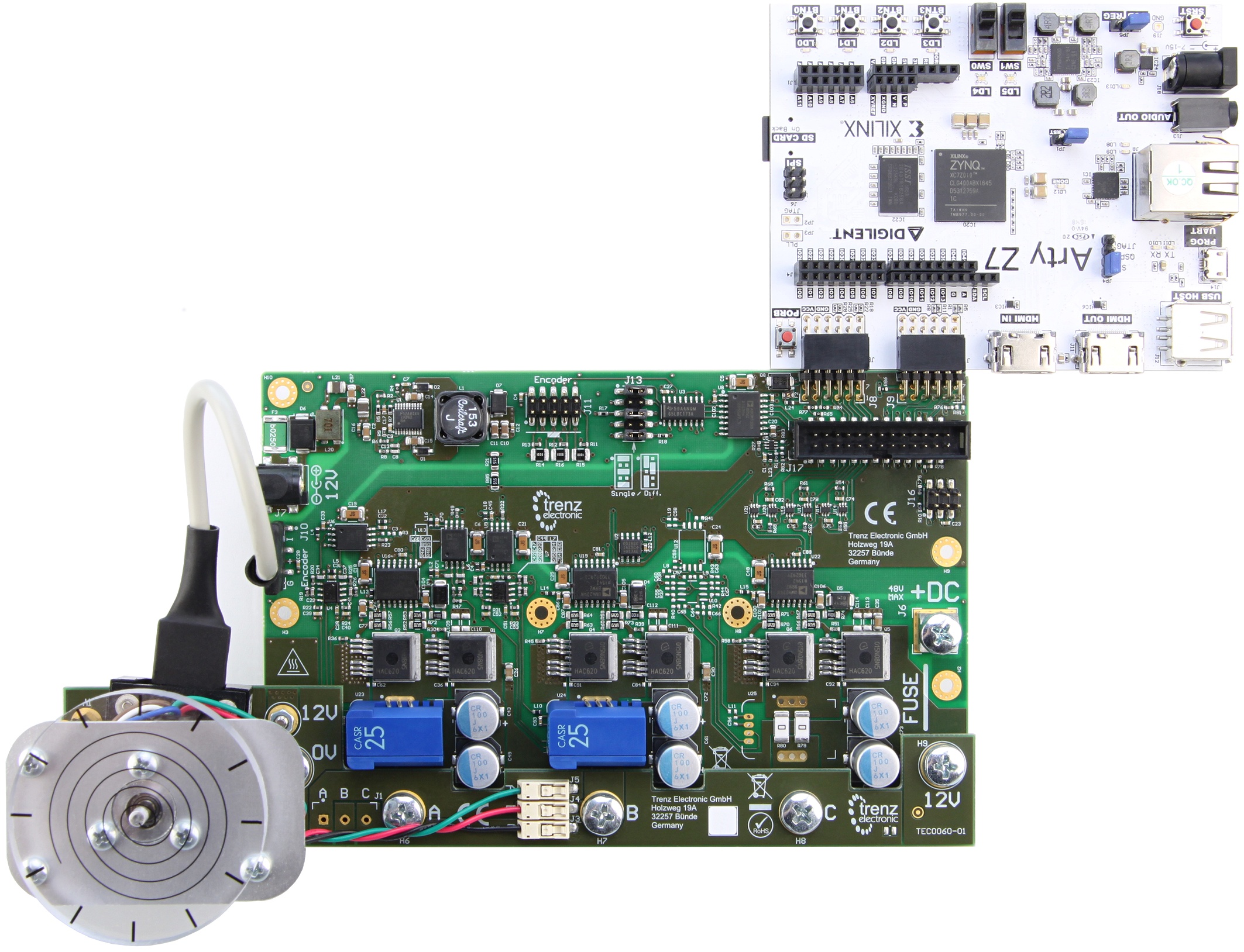
Figure 6: EDDP Kit assembly.
...
The default motor is supplied in the EDDP Kit; see the chapter Reference Motor for details. Use of custom motors is outside the scope of this manual.
Block Diagram
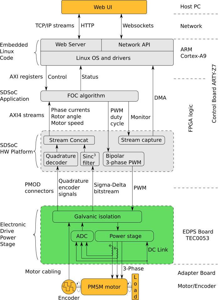
Figure 8: Block diagram of the TEC0060.
...
- The Linux OS manages the hardware and provides execution environment for the programs to run in, which includes a TCP/IP network stack. The drivers included provide access to the control and status registers of the FOC algorithm and to the DMA buffer of the monitor data stream.
- The Network API is a server program, which provides an API built on top of Websockets protocol to control and monitor the FOC algorithm and to capture the monitor data stream.
- The Web Server, which is used to host the Web UI.
The Web UI running in a web browser on the Host PC enables use of the EDDP Kit from anywhere in the network.
| Scroll Pagebreak |
|---|
List of the additional documents
...
Overview
Content Tools