Page History
...
| Scroll pdf ignore | |
|---|---|
Table of Contents
|
Overview
| Scroll Only (inline) |
|---|
Refer to https://shop.trenz-electronic.de/en/Download/?path=Trenz_Electronic/carrier_boards/TEBF0808/REV04 for downloadable version of this manual and additional technical documentation of the product.
|
The Trenz Electronic TEBF0808 carrier board is a baseboard for the Xilinx Zynq Ultrascale+ MPSoC modules TE0808 and TE0803, which exposes the module's B2B connector pins to accessible connectors and provides a whole range of on-board components to test and evaluate the Zynq Ultrascale+ SoMs and for developing purposes. The carrier board has a Mini-ITX form factor making it capable to be fitted into a PC enclosure. On the PC enclosure's rear and front panel, MGT interfaces and connectors are accessible, for the front panel elements there are also Intel-PC compatible headers available.
...
Note: These pins of the DC-DC converter U8 are hard-wired to initialiy fix the voltage to 1.8V (see schematic).
Power Rails
| Module Connector (B2B) Designator | VCC / VCCIO | Direction | Pins | Notes |
|---|---|---|---|---|
| J1 | 3.3V_MOD, | Out | Pin 151, 153, 155, 157, 159 | - |
| FMC_VADJ | Out | Pin 90, 120 | ||
| VREF_A_M2C | Out | Pin 108 | ||
| J2 | 3.3V_MOD | Out | Pin 138, 140, 142, 144, 153, 154, 155, 156, 157, 158, 159, 160 | - |
| PS_BATT | Out | Pin 125 | ||
| DDR_1V2 | In | Pin 135 (not connected to board) | ||
| J3 | 3.3V_MOD | Out | Pin 157, 158, 159, 160 | - |
| FMC_VADJ | Out | Pin 15, 16 | ||
| 1.8V | Out | Pin 43, 44 | ||
| PLL_3V3 | Out | Pin 152 | ||
| SI_PLL_1V8 | In | Pin 151 | ||
| J4 | 3.3V_MOD | Out | Pin 58, 59, 105, 106 | - |
| VREF_A_M2C | Out | Pin 15, 88 |
Table 26: Power pin description of B2B Module Connector
| FAN Designator | VCC / VCCIO | Direction | Pins | Notes |
|---|---|---|---|---|
| J35 | 12V | Out | Pin 2 | FAN2 Header |
| J26 | 12V | Out | Pin 2 | FAN1 Header |
| J19 | FAN_FMC | Out | Pin 2 | FMC FAN Header |
Table 27: Power pin description of FAN Connector
| FMC Designator | VCC / VCCIO | Direction | Pins | Notes |
|---|---|---|---|---|
| J5 | 12V | Out | Pin C35, G37 | - |
| 3.3V_PER | Out | Pin D32, D36, D38, D40, C39 | - | |
| FMC_VADJ | Out | Pin E39, G39, H40, F40 | adjustable FMC VCCIO | |
| VREF_A_M2C | In | Pin H1 | IO reference voltage |
Table 28: Power pin description of FMC Connector
| Main Power ATX + LED/RST Designator | VCC / VCCIO | Direction | Pins | Notes |
|---|---|---|---|---|
| J20 | 12V | In | Pin 10, 11 | ATX-24 Connector |
| 5VSBIN | In | Pin 9 | ||
| J25 | 12V | In | Pin 1 | 12V Power Jack Attention: optional, use only if ATX-24 Connector is not connected |
| J10 | 5V | Out | Pin 9 | Power-/HD-LED/Reset Header |
Table 29: Power pin description of ATX-24 Connector and Power-/HD-LED/Reset Header
| PMOD Designator | VCC / VCCIO | Direction | Pins | Notes |
|---|---|---|---|---|
| P1 | 3.3V_PER | Out | Pin 6, 12 | - |
| P2 | 3.3V_PER | Out | Pin 6, 12 | - |
| P3 | 3.3V_PER | Out | Pin 6, 12 | - |
Table 30: Power pin description of PMOD Connector
| XMOD / JTAG Designator | VCC / VCCIO | Direction | Pins | Notes |
|---|---|---|---|---|
| J12 | 3.3VSB | Out | Pin 5 | XMOD Header |
| 1.8V | Out | Pin 6 | ||
| J28 | 3.3VSB | Out | Pin 5, 6 | XMOD Header |
| J30 | 3.3VSB | Out | Pin 1 | ARM JTAG Header |
Table 31: Power pin description of XMOD/JTAG Connector
| Peripheral Designator | VCC / VCCIO | Direction | Pins | Notes |
|---|---|---|---|---|
| J23 | 3.3VSB | Out | Pin 1 | PC Compatible BEEPER |
| J11 | 12V | Out | Pin A2, A3, B1, B2, B3 | PCIe Connector |
| 3.3V_PCI | Out | Pin A9, A10, B8, B10 | ||
| J29 | 5V | Out | Pin 5 | CAN-Bus Header |
| J13 | DP_TX_PWR | Out | Pin 20 | Display-Port Connector |
| J14A | 3.3V_PCI | Out | Pin T15, T16 | SFP+ 2x1 Connector |
| J14B | 3.3V_PCI | Out | Pin L15, L16 | SFP+ 2x1 Connector |
| J15 | 3.3V_PER | Out | Pin 1, 10 | FireFly Connector |
| J22 | 3.3V_PER | Out | Pin 1, 10 | FireFly Connector |
| J7A | VBUS4 | Out | Pin U1 | USB3.0 Connector |
| J7B | VBUS3 | Out | Pin U10 | USB3.0 Connector |
| J8 | VBUS1 | Out | Pin 19 | USB3.0 Header |
| VBUS2 | Out | Pin 1 | ||
| J16 | 3.3V_SD_A | Out | Pin 4 | MicroSD Card Socket |
| J27 | 3.3V_SD_B | Out | Pin 4 | MMC Card Socket |
| B1 | VBATT | In | Pin + | Battery Holder |
Table 32: Power pin description of Peripherals' Connector
B2B connectors
| Include Page | ||||
|---|---|---|---|---|
|
...
Parameter | Min | Max | Unit | Notes / Reference Document |
|---|---|---|---|---|
| Power supply voltage (12V nominal) | 11.4 | 12.6 | V | ANSI/VITA 57.1 FPGA Mezzanine Card (FMC) standard |
| Battery Voltage PSBATTVBATT | -0.5 | 2 | V | Xilinx DS925 data sheet |
| Voltage on pins of PMOD P2 | -0.5 | 3.75 | V | MachXO2 Family Data Sheet |
Storage temperature (ambient) | -55 | 85 | °C | Marvell 88E1512 datasheet |
Table 33: Board absolute maximum ratings.
| Note |
|---|
| Assembly variants for higher storage temperature range are available on request. |
...
| Parameter | Min | Max | Unit | Notes / Reference Document |
|---|---|---|---|---|
| Power supply voltage (12V nominal) | 11.4 | 12.6 | V | ANSI/VITA 57.1 FPGA Mezzanine Card (FMC) standard |
| Battery Voltage PSBATTVBATT | 1.2 | 1.5 | V | Xilinx DS925 data sheet |
| Voltage on pins PMOD P1P2 | 3.135 | 3.6 | V | MachXO2 Family Data Sheet |
Table 34: Board recommended operating conditions.
| Note |
|---|
| Please check TRM TE0808 / TE0803 and Xilinx datasheet DS925 for complete list of absolute maximum and recommended operating ratings for the mounted UltraSoM+. |
...
All dimensions are given in millimeters.
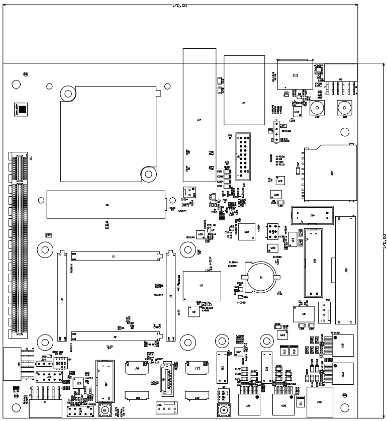
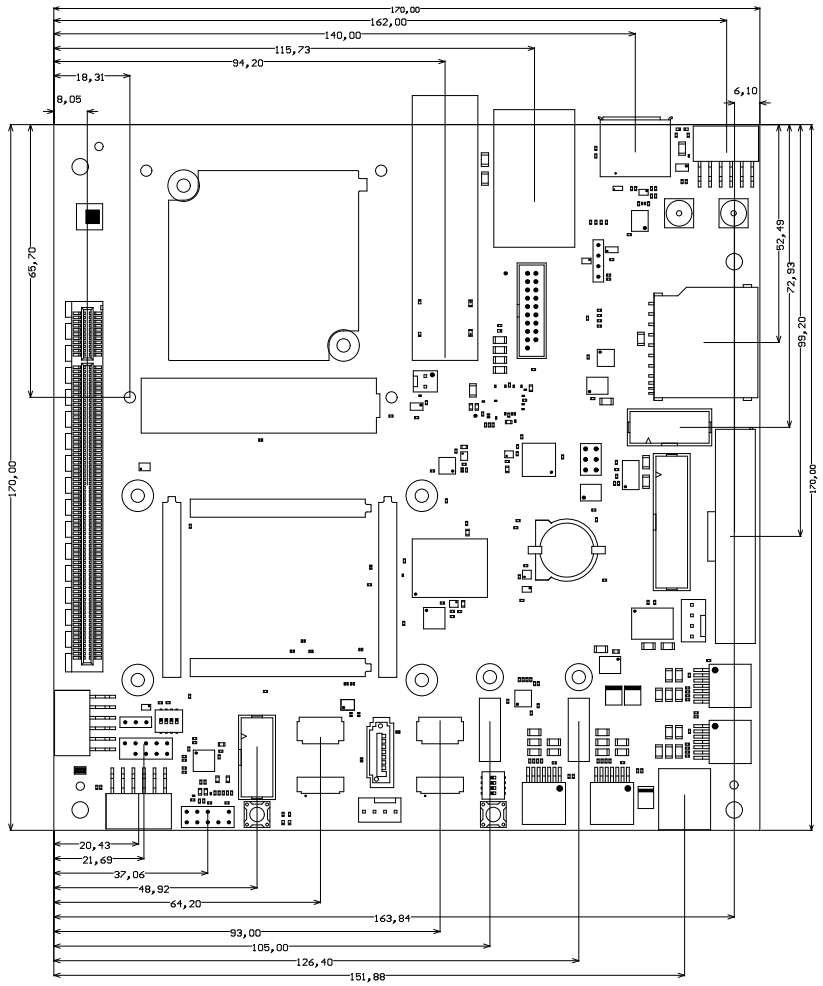
Figure 14: Board physical dimensions drawing.
Revision History
Hardware Revision History
| Date | Revision | Notes | Link to PCN | Documentation Link |
|---|---|---|---|---|
| - | 04 | Current available board revision | - | TEBF0808-04 |
| - | 03 | Second production release | - | TEBF0808-03 |
| - | 02 | First production release | - | TEBF0808-02 |
| - | 01 | Prototype | - | - |
Table 35: Board hardware revision history.
Hardware revision number is written on the PCB board together with the module model number separated by the dash.
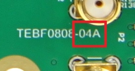
Figure 15: Board hardware revision number.
Document Change History
| Date | Revision | Contributors | Description | ||||||||
|---|---|---|---|---|---|---|---|---|---|---|---|
| Ali Naseri |
| |||||||||
2017-08-29 | v.70 | John Hartfiel |
| ||||||||
| 2017-08-28 | v.69 | Ali Naseri |
|
Table 36: Document change history.
Disclaimer
| Include Page | ||||
|---|---|---|---|---|
|
Overview
Content Tools